


April 27, 2004 Manual Version 1.01
3.2
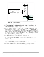
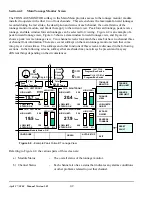
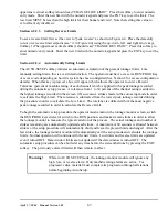
Figure 3.2:
Tonnages From Example Die 1
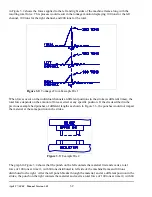
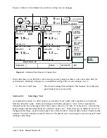
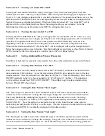
Figure 3.3:
Example Die 2
in Figure 3.2 shows the forces applied to the left and right sides of the machine frame along with the
resulting total force. This process would result in the tonnage monitor displaying 100 tons for the left
channel, 100 tons for the right channel, and 200 tons for the total.
When forces occur on the individual channels at different positions in the stroke (at different times), the
total force depends on the amount of force exerted at any specific position. If the die described in the
previous example had punches of different lengths as shown in Figure 3.3, the punches would not impact
the material at the same position in the stroke.
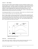
The graph in Figure 3.4 shows that the punch on the left contacts the material first and exerts a total
force of 100 tons at time t1, with 60 tons distributed to left side of the machine frame and 40 tons
distributed to the right. After the left punch breaks through the material, and at a different position in the
stroke, the punch on the right contacts the material and exerts a total force of 100 tons at time t2, with 60
Содержание OmniLink II
Страница 5: ...April 27 2004 Manual Version 1 01 iv ...
Страница 7: ...April 27 2004 Manual Version 1 01 1 2 ...
Страница 21: ...April 27 2004 Manual Version 1 01 3 8 ...
Страница 43: ...April 27 2004 Manual Version 1 01 4 22 Section 4 5 3 3 N A Section 4 5 3 4 N A Section 4 5 3 5 N A ...
Страница 44: ...April 27 2004 Manual Version 1 01 4 23 Section 4 5 4 N A ...
Страница 45: ...April 27 2004 Manual Version 1 01 4 24 ...
Страница 69: ...April 27 2004 Manual Version 1 01 7 14 ...
Страница 77: ...April 27 2004 Manual Version 1 01 8 8 ...
Страница 79: ...April 27 2004 Manual Version 1 01 9 2 ...
Страница 81: ...April 27 2004 Manual Version 1 01 10 2 ...