1
Top
229 mm (9 in.)
2
Rear
101.6 mm (4 in.)
3
Right side 178 mm (7 in.)
4
Front
508 mm (20 in.)
5
Left side
127 mm (5 in.)
Attaching cables
CAUTION—SHOCK HAZARD:
To avoid the risk of electrical shock, do not set up this product or make
any electrical or cabling connections, such as the power cord, fax feature, or telephone, during a
lightning storm.
CAUTION—POTENTIAL INJURY:
To avoid the risk of fire or electrical shock, connect the power cord to
an appropriately rated and properly grounded electrical outlet that is near the product and easily
accessible.
CAUTION—POTENTIAL INJURY:
To avoid the risk of fire or electrical shock, use only the power cord
provided with this product or the manufacturer's authorized replacement.
CAUTION—POTENTIAL INJURY:
To reduce the risk of fire, use only a 26 AWG or larger
telecommunications (RJ-11) cord when connecting this product to the public switched telephone
network. For users in Australia, the cord must be approved by the Australian Communications and Media
Authority.
Warning—Potential Damage:
To avoid loss of data or printer malfunction, do not touch the USB cable, any
wireless network adapter, or the printer in the areas shown while actively printing.
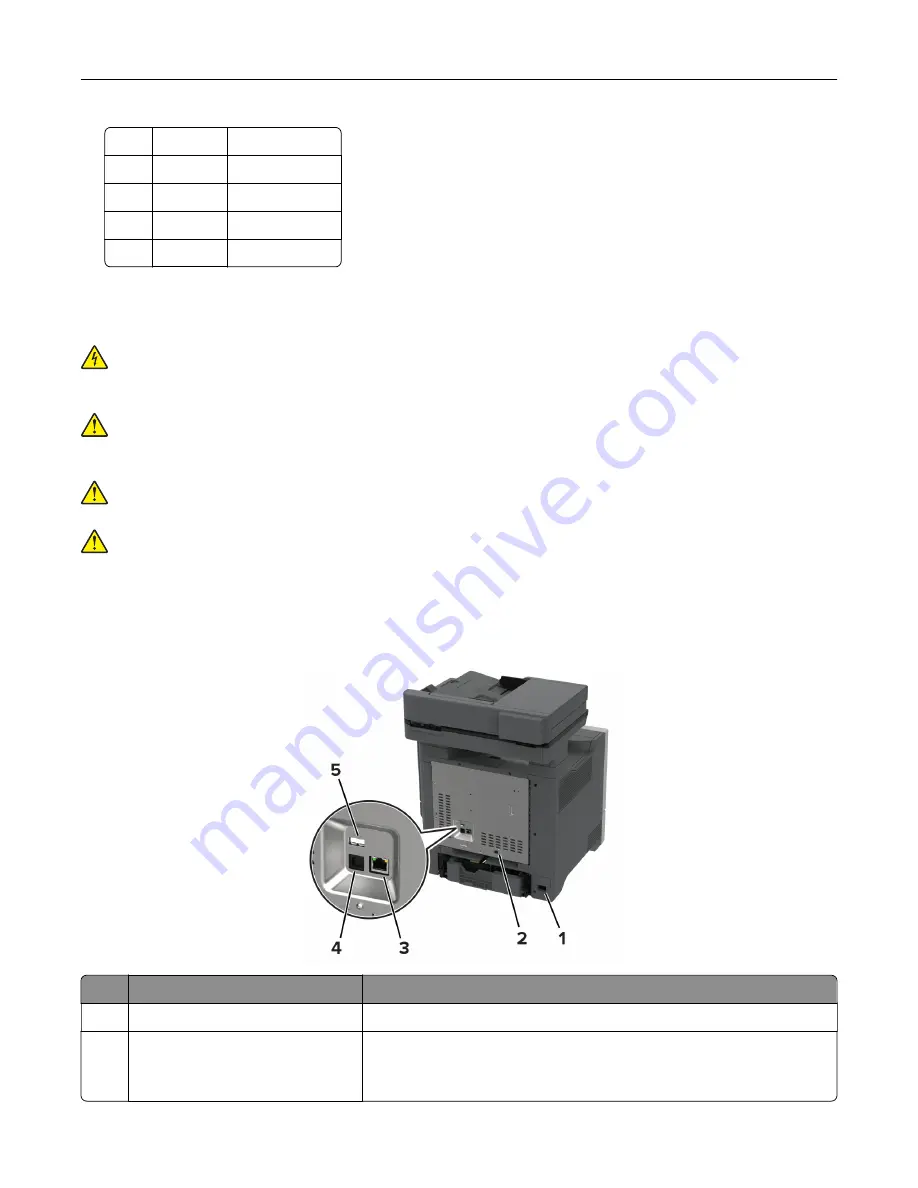
Printer port
Function
1
Power cord socket
Connect the printer to a properly grounded electrical outlet.
2
LINE port
Note:
Available only in some
printer models.
Connect the printer to an active telephone line through a standard wall
jack (RJ
‑
11), DSL filter, or VoIP adapter, or any other adapter that allows
you to access the telephone line to send and receive faxes.
Set up, install, and configure
21
Содержание XC4342
Страница 58: ...4 Locate the ISD connector 5 Insert the card to the ISD connector Set up install and configure 58 ...
Страница 64: ...3 Remove the fax cover 4 Remove the fax bracket Set up install and configure 64 ...
Страница 65: ...5 Install the fax card to the bracket Set up install and configure 65 ...
Страница 66: ...6 Install the fax card and attach the connector to the controller board Set up install and configure 66 ...
Страница 70: ...4 Install the ISP into its housing Set up install and configure 70 ...
Страница 71: ...5 Attach the housing to the controller board shield Set up install and configure 71 ...
Страница 72: ...6 Connect the ISP extended cable to the ISP connector in the controller board Set up install and configure 72 ...
Страница 76: ...Set up install and configure 76 ...
Страница 79: ...4 Attach the cover of the power supply until it clicks into place Set up install and configure 79 ...
Страница 81: ...7 Insert the power supply through the printer 8 Install the convenience stapler Set up install and configure 81 ...
Страница 84: ...Set up install and configure 84 ...
Страница 85: ...3 Install the wireless module into its housing Set up install and configure 85 ...
Страница 86: ...4 Attach the wireless module to the controller board shield Set up install and configure 86 ...
Страница 87: ...5 Connect the wireless assembly to the ISP connector in the controller board Set up install and configure 87 ...
Страница 88: ...6 Attach the controller board shield Set up install and configure 88 ...
Страница 204: ...Replacing parts and supplies Replacing a toner cartridge 1 Open door B Maintain the printer 204 ...
Страница 205: ...2 Remove the used toner cartridge 3 Unpack the new toner cartridge Maintain the printer 205 ...
Страница 206: ...4 Insert the new toner cartridge 5 Close door B Maintain the printer 206 ...
Страница 207: ...Replacing the black imaging unit 1 Open door B Maintain the printer 207 ...
Страница 209: ...3 Remove the toner cartridges Maintain the printer 209 ...
Страница 210: ...4 Disconnect the imaging kit cable Maintain the printer 210 ...
Страница 214: ...9 Insert the imaging kit Maintain the printer 214 ...
Страница 216: ...Replacing the color imaging kit 1 Open door B Maintain the printer 216 ...
Страница 218: ...3 Remove the toner cartridges Maintain the printer 218 ...
Страница 219: ...4 Disconnect the imaging kit cable Maintain the printer 219 ...
Страница 220: ...5 Remove the used imaging kit Maintain the printer 220 ...
Страница 222: ...8 Insert the black imaging unit into the new imaging kit Maintain the printer 222 ...
Страница 223: ...9 Insert the new imaging kit Maintain the printer 223 ...
Страница 225: ...Replacing the waste toner bottle 1 Open door B Maintain the printer 225 ...
Страница 234: ...2 Remove the used separator bracket 3 Unpack the new separator bracket Maintain the printer 234 ...
Страница 238: ...2 Remove the used ADF pick roller Maintain the printer 238 ...
Страница 240: ...5 Insert the new ADF separator roller until it clicks into place Maintain the printer 240 ...
Страница 250: ...2 Remove the ADF pick roller Maintain the printer 250 ...
Страница 252: ...5 Insert the ADF separator roller until it clicks into place Maintain the printer 252 ...
Страница 253: ...6 Insert the ADF pick roller until it clicks into place 7 Close door C Maintain the printer 253 ...
Страница 294: ...Jam locations 1 ADF 2 Standard bin 3 Door A 4 Multipurpose feeder 5 Trays Troubleshoot a problem 294 ...
Страница 298: ...2 Remove the jammed paper Note Make sure that all paper fragments are removed 3 Open door A1 Troubleshoot a problem 298 ...


