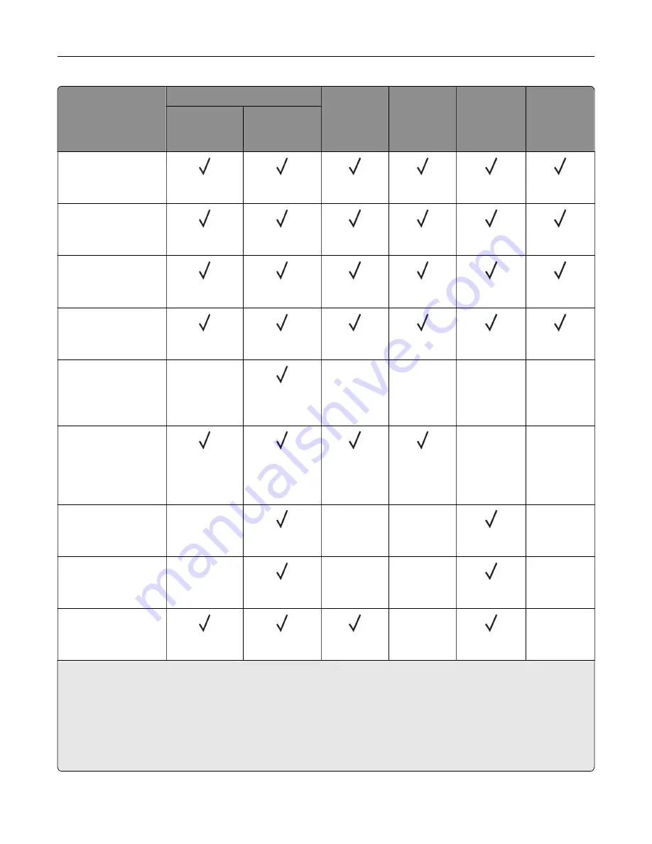
Paper size
650
‑
sheet duo tray
Optional
550
‑
sheet
tray
Two
‑
sided
printing
Scanner
ADF
550
‑
sheet
tray
100
‑
sheet
multipurpose
feeder
Legal
215.9 x 355.6 mm
(8.5 x 14 in.)
Letter
215.9 x 279.4 mm
(8.5 x 11 in.)
Oficio (Mexico)
216 x 340 mm
(8.5 x 13.4 in.)
Statement
139.7 x 215.9 mm
(5.5 x 8.5 in.)
Universal
2, 3
76.2 x 127 mm to 215.9
x 355.6 mm
(3 x 5 in. to 8.5 x 14 in.)
X
X
X
X
X
Universal
2, 3
105 x 148 mm to 215.9
x 355.6 mm
(4.13 x 5.83 in. to 8.5 x
14 in.)
X
X
7 3/4 Envelope
98.4 x 190.5 mm
(3.875 x 7.5 in.)
X
X
X
X
9 Envelope
98.4 x 225.4 mm
(3.875 x 8.9 in.)
X
X
X
X
10 Envelope
104.8 x 241.3 mm
(4.12 x 9.5 in.)
X
X
1
Supported in both the portrait and landscape orientations. When fed in the portrait orientation, A5 is treated as
narrow paper. When fed in landscape orientation, it is treated as a regular width paper.
2
When Universal is selected, the page is formatted for 215.9 x 355.6 mm (8.5 x 14 in.) unless the size is specified
by the software application.
3
Load narrow paper in portrait orientation.
4
When Other Envelope is selected, the page is formatted for 215.9 x 355.6 mm (8.5 x 14 in.) unless a size is specified
by the software application.
Learn about the printer
16
Содержание XC4342
Страница 58: ...4 Locate the ISD connector 5 Insert the card to the ISD connector Set up install and configure 58 ...
Страница 64: ...3 Remove the fax cover 4 Remove the fax bracket Set up install and configure 64 ...
Страница 65: ...5 Install the fax card to the bracket Set up install and configure 65 ...
Страница 66: ...6 Install the fax card and attach the connector to the controller board Set up install and configure 66 ...
Страница 70: ...4 Install the ISP into its housing Set up install and configure 70 ...
Страница 71: ...5 Attach the housing to the controller board shield Set up install and configure 71 ...
Страница 72: ...6 Connect the ISP extended cable to the ISP connector in the controller board Set up install and configure 72 ...
Страница 76: ...Set up install and configure 76 ...
Страница 79: ...4 Attach the cover of the power supply until it clicks into place Set up install and configure 79 ...
Страница 81: ...7 Insert the power supply through the printer 8 Install the convenience stapler Set up install and configure 81 ...
Страница 84: ...Set up install and configure 84 ...
Страница 85: ...3 Install the wireless module into its housing Set up install and configure 85 ...
Страница 86: ...4 Attach the wireless module to the controller board shield Set up install and configure 86 ...
Страница 87: ...5 Connect the wireless assembly to the ISP connector in the controller board Set up install and configure 87 ...
Страница 88: ...6 Attach the controller board shield Set up install and configure 88 ...
Страница 204: ...Replacing parts and supplies Replacing a toner cartridge 1 Open door B Maintain the printer 204 ...
Страница 205: ...2 Remove the used toner cartridge 3 Unpack the new toner cartridge Maintain the printer 205 ...
Страница 206: ...4 Insert the new toner cartridge 5 Close door B Maintain the printer 206 ...
Страница 207: ...Replacing the black imaging unit 1 Open door B Maintain the printer 207 ...
Страница 209: ...3 Remove the toner cartridges Maintain the printer 209 ...
Страница 210: ...4 Disconnect the imaging kit cable Maintain the printer 210 ...
Страница 214: ...9 Insert the imaging kit Maintain the printer 214 ...
Страница 216: ...Replacing the color imaging kit 1 Open door B Maintain the printer 216 ...
Страница 218: ...3 Remove the toner cartridges Maintain the printer 218 ...
Страница 219: ...4 Disconnect the imaging kit cable Maintain the printer 219 ...
Страница 220: ...5 Remove the used imaging kit Maintain the printer 220 ...
Страница 222: ...8 Insert the black imaging unit into the new imaging kit Maintain the printer 222 ...
Страница 223: ...9 Insert the new imaging kit Maintain the printer 223 ...
Страница 225: ...Replacing the waste toner bottle 1 Open door B Maintain the printer 225 ...
Страница 234: ...2 Remove the used separator bracket 3 Unpack the new separator bracket Maintain the printer 234 ...
Страница 238: ...2 Remove the used ADF pick roller Maintain the printer 238 ...
Страница 240: ...5 Insert the new ADF separator roller until it clicks into place Maintain the printer 240 ...
Страница 250: ...2 Remove the ADF pick roller Maintain the printer 250 ...
Страница 252: ...5 Insert the ADF separator roller until it clicks into place Maintain the printer 252 ...
Страница 253: ...6 Insert the ADF pick roller until it clicks into place 7 Close door C Maintain the printer 253 ...
Страница 294: ...Jam locations 1 ADF 2 Standard bin 3 Door A 4 Multipurpose feeder 5 Trays Troubleshoot a problem 294 ...
Страница 298: ...2 Remove the jammed paper Note Make sure that all paper fragments are removed 3 Open door A1 Troubleshoot a problem 298 ...


