l
IMS94S-mv1
32
6.2 Motor Group
Motor group shows currently selected motor. You can click “CLICK HERE TO
CHANGE” to view selected motor parameters or select new motor. Please refer to
Section 5.5 for details on how to select motor.
6.3 Parameters Group
6.3.1 Drive operating modes
The SimpleServo has 3 operating modes: Torque, Velocity and Position. Depending
on what servo system you want to build you will choose on of these modes.
For Torque and Velocity modes
drive will accept an analog input voltage on the
AIN+ and AIN- pins of P3. This voltage is used to provide torque or speed reference.
For Position mode
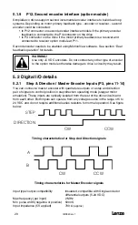
drive will accept step and direction logic signals or a quadrature
pulse train.
6.3.1.1 Velocity mode
In velocity mode, the servo control regulates motor shaft speed (velocity)
proportional to analog input voltage.
Target speed ( set speed ) is calculated using formula:
Set Velocity (RPM) = Vinput (Volt) X Vscale (RPM/Volt)
where:
Vinput - voltage at analog input
Vscale - velocity scale factor (input sensitivity) set by 6.3.6 - Analog input
(Velocity scale) parameter.
6.3.1.2 Torque mode
In torque mode, the SimpleServo control provides a current output proportional to
the analog input signal, up to the maximum output current rating of the drive. Set
Current (current the drive will try to provide) is calculated using formula:
Set Current(A) = Vinput(Volt) X Iscale (A/Volt)
where:
Vinput - voltage at analog input
Vscale - current scale factor (input sensitivity) set by 6.5.2 - Analog input (Current
Scale) parameter.
6.3.1.3 Position mode
In this mode the drive reference is a pulse-train applied to P3-11,12 and P3-
13,14 terminals. Input can be configured for two types of signals: step and
direction and Master encoder quadrature signal. Refer to section 5.2.1 for details
on these inputs connections. Refer to section 8.3 for details about positioning
and gearing.
6.3.2 Drive PWM frequency
Parameter sets PWM carrier frequency. Frequency can be changed only when drive
is disabled.
6.3.3 Current Limit
The CURRENT LIMIT setting determines the nominal current, in amps RMS per phase.
Содержание SimpleServo 94
Страница 1: ...MODEL 94 USERS MANUAL IMS94S mv1 ...
Страница 12: ...l IMS94S mv1 10 3 2 Clearance for Cooling Air Circulation ...
Страница 56: ...l IMS94S mv1 54 ...
Страница 57: ...IMS94S mv1 l 55 ...
Страница 58: ...l IMS94S mv1 56 ...
Страница 59: ...IMS94S mv1 l 57 ...
Страница 60: ...l IMS94S mv1 58 ...
Страница 61: ...IMS94S mv1 l 59 ...
Страница 62: ...l IMS94S mv1 60 ...
Страница 63: ...IMS94S mv1 l 61 ...
Страница 64: ...l IMS94S mv1 62 ...
Страница 65: ...IMS94S mv1 l 63 ...

