background image

l

IMS94S-mv1

60

Содержание SimpleServo 94

Страница 1: ...MODEL 94 USERS MANUAL IMS94S mv1 ...

Страница 2: ...pect to this material including but not limited to the implied warranties of its merchantability and fitness for a given purpose Lenze AG and its Divisions assume no responsibility for any errors that may appear in this manual and make no commitment to update or to keep current the information in this manual MotionView SimpleServo and all related indicia are either registered trademarks or trademar...

Страница 3: ... 4 P4 Motor Feedback second loop encoder input 17 5 1 5 P5 24 VDC Back up Power Input 18 5 1 6 P6 Dynamic Braking and DC Bus 18 5 1 7 Connectors and Wiring Notes 19 5 1 8 P11 Resolver interface option module 19 5 1 9 P12 Second encoder interface option module 20 5 2 Digital I O details 20 5 2 1 Step Direction Master Encoder Inputs P3 pins 11 14 20 5 2 2 Digital outputs 21 5 2 3 Digital inputs 21 5...

Страница 4: ...le 34 6 3 16 Encoder repeat source 34 6 3 17 Master to system ratio 35 6 3 18 Second to prime encoder ratio 35 6 4 Communication 35 6 4 1 RS 485 configuration 35 6 4 2 Modbus baud rate 35 6 4 3 Modbus reply delay 35 6 5 Analog I O Group 35 6 5 1 Analog output 35 6 5 2 Analog output current scale Volt amps 35 6 5 3 Analog output velocity scale mV RPM 35 6 5 4 Analog input offset parameter 35 6 5 5 A...

Страница 5: ...45 8 5 Enabling the SimpleServo 45 8 6 Tuning in velocity mode 46 8 7 Tuning in position mode 47 9 Sample Motor Responses to Gain Settings 48 9 1 Motor response to gain settings Velocity mode 48 9 1 1 Low P gain 48 9 1 2 Correct P gain 48 9 1 3 I gain too high 49 9 1 4 Correct P gain and I gain 49 9 2 Motor response to gain settings Position Mode 50 9 2 1 Non optimal P gain D gain relationship 50 ...

Страница 6: ...t indicates additional information shortcuts or tips that do not affect the safe operation of the drive Reduce the chance of an electrical fire shock or explosion by proper grounding over current protection thermal protection and enclosure Follow sound maintenance procedures It is possible for a drive to run at full speed as a result of a component failure Please ensure that a master switch has bee...

Страница 7: ...nnel information or from a resolver It accepts commands from a variety of sources including analog voltage Modbus RTU interface CAN interface and quadrature digital pulse train The control will operate in current torque mode velocity mode or position step and direction master encoder mode The SimpleServo s built in RS 232 serial communications port and SimpleServo control program MotionView make p...

Страница 8: ...nces but only for industrial purposes Drive systems with E94S servo inverters comply with the EMC Directive if they are installed according to the guidelines of CE typical drive systems can be used for operation on public and non public mains for operation in industrial premises and residential areas The user is responsible for the compliance of his application with the EC directives Any other use...

Страница 9: ...oubles the voltage on motor output terminals U V W for use with 230VAC motors 3 Connection of 230VAC or 120VAC to input power terminals L1 and L2 on these models delivers an equal voltage as maximum to motor output terminals U V W allowing operation with either 120VAC or 230VAC motors 4 Drive rated at 8kHz Carrier Frequency Derate Continuous current by 30 at 16kHz 5 Peak RMS current allowed for up...

Страница 10: ...E P2 Encoder Feedback primary Standard 15 pin D shell P4 Encoder Feedback secondary Option module with standard 9 pin D shell P12 Resolver feedback Option module with standard 9 pin D shell P11 Encoder buffered repeat In 25 pin D shell controller connector P3 Mains Power 4 pin removable terminal block P1 Motor Power 6 pin pin removable terminal block P7 Regen and Bus Power 5 pin removable terminal...

Страница 11: ...4S040S1N 69 190 235 1 6 E94S020S2F 67 190 235 1 3 E94S040S2F 69 190 235 1 5 E94S080S2F 95 190 235 1 9 E94S100S2F 115 190 235 2 2 E94S020Y2N 67 190 190 1 3 E94S040Y2N 69 190 190 1 5 E94S080Y2N 95 190 190 1 9 E94S100Y2N 115 190 190 2 2 E94S020T4N 69 190 190 1 5 E94S040T4N 95 190 190 1 9 E94S050T4N 115 190 190 2 2 ...

Страница 12: ...l IMS94S mv1 10 3 2 Clearance for Cooling Air Circulation ...

Страница 13: ...thin the specified ambient operating temperature range Additional cooling with an external fan may be recommended in certain applications Avoid excessive vibration to prevent intermittent connections DO NOT connect incoming mains power to the output motor terminals U V W Severe damage to the SimpleServo will result Do not disconnect any of the motor leads from the SimpleServo unless mains power is ...

Страница 14: ... sure all cables are shielded and properly grounded It may be necessary to earth ground the shielded cable Ground the shield at the SimpleServo end and at the motor end If the SimpleServo continues to pick up noise after grounding the shield it may be necessary to add an AC line filtering device and or an output filter between drive and servo motor 4 2 2 EMI Protection Electromagnetic interference E...

Страница 15: ...hine ground If the end user is using a CE approved motor the AC filter combined with the recommended SimpleServo motor and encoder cables is all that is necessary to meet the EMC directives listed herein The end user must use the compatible filter to comply with CE specifications The OEM may choose to provide alternative filtering that encompasses the SimpleServo and other electronics within the same ...

Страница 16: ... to 480 VAC above earth ground Avoid direct contact with the printed circuit board or with circuit elements to prevent the risk of serious injury or fatality Disconnect incoming power and wait 60 seconds before servicing drive Capacitors retain charge after power is removed DO NOT connect incoming power to the output motor terminals U V W Severe damage to the SimpleServo will result All conductors...

Страница 17: ...t is used to communicate with a host computer via standard RS 232 interface This port is present on all SimpleServo drives All levels must be RS 232C compliant TABLE 4 P2 PIN ASSIGNMENTS Pin Name Function 1 RESERVED 2 TX RS 232 transmit 3 RX RS 232 receive 4 RESERVED 5 GND Common 6 RESERVED 7 RESERVED 8 RESERVED 9 RESERVED WARNING Do not make any connection to Reserved pins Note If you purchase se...

Страница 18: ...ogrammable 11 MA Step Master Encoder A Step input 2 12 MA Step Master Encoder A Step input 2 13 MB Dir Master Encoder B Direction input 14 MB Dir Master Encoder B Direction input 15 OUT1 C Programmable output 1 Collector 16 OUT1 E Programmable output 1 Emitter 17 IN1 Digital Input 1 Enable 3 18 IN_COM Digital Input Common 19 OUT2 C Programmable output 2 Collector 20 OUT2 E Programmable output 2 Em...

Страница 19: ...d Encoder Output channel A on P3 The Hall sensors from the motor must be wired to the 15 pin connector WARNING Use only 5 VDC encoders Do not connect any other type of encoder to the SimpleServo reference voltage terminals When using a front end controller it is critical that the 5 VDC supply on the front end controller NOT be connected to the 5 VDC supply on the SimpleServo as this will result in...

Страница 20: ...or C Input 14 HB Hall Sensor B Input 15 HC Hall Sensor C Input 1 See Note 1 Section 5 1 7 Connector and Wiring Notes 4 See Note 4 Section 5 1 7 Connector and Wiring Notes 5 1 5 P5 24 VDC Back up Power Input P5 is a 2 pin quick connect terminal block that can be used with an external 24 VDC 2 amp power supply to provide power loss logic ride through capability During a power loss the logic and comm...

Страница 21: ... exception when motor with resolver is used In this case channels A and B are derived from resolver signals The encoder channel A pin on P4 for example is buffered and routed to the encoder channel A pin on P3 inside the SimpleServo If you require encoder information wire your controller to P3 The encoder and Hall sensor feedback from the motor must be wired to the 15 pin Type D receptacle connect...

Страница 22: ... option module otherwise damage to drive s circuitry may result 5 2 Digital I O details 5 2 1 Step Direction Master Encoder Inputs P3 pins 11 14 You can connect a master encoder with quadrature outputs or a step and direction pair of signals to control position in step direction operating mode stepper motor emulation These inputs are optically isolated from the rest of the drive circuits and from ...

Страница 23: ...puts OUT1 and OUT2 available on P3 Outputs are fully isolated from the rest of the drive circuits dry contacts See figure below for its electrical diagram Output polarity is programmable i e each output can be programmed for N O or N C operation Each output can be assigned to one of the following functions Zero speed In speed window Current limit Run time fault Ready Brake release Digital outputs e...

Страница 24: ...connections must be referenced to Analog Common P3 pin 25 of the drive This input is used to control speed or torque of the motor in velocity or torque mode The total reference voltage as seen by the drive is the voltage difference between AIN and AIN If used in single ended mode one of the inputs must be connected to a voltage source while the other one must be connected to Analog Common If used ...

Страница 25: ...e will resend this command over the RS485 interface thus making it available for another device in the network The same will happen if a command is received over the RS485 interface all devices whose addresses do not match will repeat the command on their RS232 ports This feature is useful when you need to access drives on RS485 network using RS232 interface Usually a PC computer is not equipped w...

Страница 26: ... cable must be connected to encoder terminal P4 if the motor is equipped with an incremental encoder If the motor is equipped with a resolver it needs to be connected to terminal P11 on the resolver option module 5 5 2 Motor over temperature protection Terminals P7 1 T1 and P7 2 T2 are dedicated for a motor PTC temperature sensor connection Use parameter Motor PTC cut off resistance see 6 3 12 to ...

Страница 27: ...hanges 5 6 1 Setting custom motor parameters WARNING Use extreme caution when entering custom parameters Incorrect settings may cause damage to the drive or motor If you are unsure of the settings refer to the materials that were distributed with your motor or contact the motor manufacturer for assistance 1 Enter custom motor data in the motor parameters dialog fields Complete all sections of dialo...

Страница 28: ...g will determine resolver angle value offset and angle increment direction CW for positive Parameter To perform autophasing 1 Complete steps in Section 5 6 1 Setting custom motor parameters above If the motor file you are trying to autophase already exists on your hard drive simply load it per Selecting custom motor section above 2 Make sure that the motor s shaft is not connected to any mechanical...

Страница 29: ... to phase winding Resistance will typically be between R 0 5 Ohms and R 200 Ohms Phase to phase winding Inductance L This must be set in millihenries mH The phase to phase winding Inductance will typically be between L 0 5 mH and L 200 0 mH Note If the units for the phase to phase winding Inductance L are given in micro henries mH then divide by 1000 to get mH Nominal phase current RMS Amps Maximu...

Страница 30: ...or the drive and the correct voltage will be calculated dynamically depending on the drive s incoming voltage value Rotor Moment of Inertia Jm From motor manufacturer or nameplate set to 0 if unknown Note Round the calculated result to 3 significant places Maximum Motor Speed in RPM This is also listed as Speed Vt motor speed at the terminal voltage rating The maximum motor speed will typically be ...

Страница 31: ...ts where it crosses the horizontal line zero The dashed lines at the zero crossings above indicate that Hall B output is lined up with and in phase with the R Output Voltage 2 Look at the S Output Voltage Determine which Hall Voltage is in phase with this Voltage As can be seen Hall C output is in phase with the S Output Voltage 3 Look at the T Output Voltage Determine which Hall Voltage is in pha...

Страница 32: ...aft rotating CW when looking at the mounting face of the motor For that rotation Encoder phase A must lead phase B If it does leave check box unchecked Otherwise if B leads A check B leads A for CW box Note Some manufacturers timing diagrams are CW when viewed from the rear of the motor not from shaft 5 6 3 3 For resolver equipped motors only If parameter Resolver is checked following parameters a...

Страница 33: ...PM operation When the drive is powered up it first checks for a blue EPM in the EPM Port If the EPM Port is empty or has a different color EPM inserted no further operation is possible until a blue EPM is installed into the EPM Port The drive will display EP until a blue EPM is inserted If a blue EPM is detected the drive compares data in the EPM to that in its internal memory In order for the driv...

Страница 34: ...Vinput voltage at analog input Vscale velocity scale factor input sensitivity set by 6 3 6 Analog input Velocity scale parameter 6 3 1 2 Torque mode In torque mode the SimpleServo control provides a current output proportional to the analog input signal up to the maximum output current rating of the drive Set Current current the drive will try to provide is calculated using formula Set Current A V...

Страница 35: ...ed when drive operates in Velocity mode Units for this parameter are RPM Volt To calculate value use following formula Vscale VelocityMax Vin max Velocitymax maximum desired velocity in RPM Vin max max voltage fed to analog input at Velocitymax Example Velocitymax 2000 RPM Vin max 10V Vscale Velocitymax Vin max 2000 10V 200 RPM Volt value to enter 6 3 7 ACCEL DECEL Limits Velocity mode only The AC...

Страница 36: ... the step and direction input to make one full revolution of the motor shaft This number can be negative effectively reversing motor rotation Used also to set gear ratio if drive following a master motor 6 3 14 Second encoder Disables or enables second encoder Effectively selects single loop or double loop configuration in position mode Second encoder option module connector P12 is used to connect ...

Страница 37: ...485 interface in Modbus RTU mode When drive is operating in normal mode baud rate is set to the same as for RS232 interface 6 4 3 Modbus reply delay This parameter sets time delay between drive reply to Modbus RTU master This delay is needed for some types of Modbus masters to function correctly 6 5 Analog I O Group 6 5 1 Analog output SimpleServo has one analog output with 10 bit resolution Signa...

Страница 38: ...erse Sign of input reference voltage is reversed 6 6 2 Programmable digital output 1 and 2 Simple Servo has two digital outputs that can be separately assigned for the following functions Not assigned No function has been assigned for digital output Zero Speed Motor is at zero speed threshold set by ZERO SPEED parameters in Velocity Limits Group In Speed Window Motor shaft RPM is within specified s...

Страница 39: ...T SPEED condition can also trigger a programmable digital output if selected For example if AT SPEED is set for 1000 RPM and the SPEED WINDOW is set for 100 then AT SPEED will be true when the motor velocity is between 950 1050 RPM 6 8 Position limits Position error Max error time Second encoder position error Second encoder max error time POSITION ERROR specifies maximum allowable error in quadrat...

Страница 40: ...ng at low speed or in a steady state without rapid or frequent changes in position Position D gain Differential The output of the D term portion of the filter proportional to difference between current position error and position error measured in previous servo cycle D term decreases bandwidth and increases overall system stability It responsible for removing oscillation caused by load inertia and...

Страница 41: ...adjustable period Sweep Time and magnitude Reference Slider for easy tuning 6 11 2 Drive monitor Drive monitor shows you the motor hall sensor states and actual motor encoder counts This tool is useful when troubleshooting the motor s encoder connections 6 11 3 Oscilloscope tool Oscilloscope tool gives real time representation of different signals inside the SimpleServo drive and is helpful when d...

Страница 42: ...x xx Hardware revision ex H1 00 Fx xx Firmware revision ex F1 00 OPEr Operating mode to set POS position mode UEL velocity mode torq torque mode CAnU CANBUS velocity mode CAnt CANBUS torque mode bAud RS232 RS485 normal mode baud rate to set selects 38 4 19 2 9 6 kbps baudrate Adr Drive s address to set sets 0 31 drive s address FLtS Stored fault s history to view scroll trough stored faults F0XX t...

Страница 43: ...LED will flash when changing D Comm Fault Red LED illuminates upon a communication fault E Comm Activity Green LED flashes to indicate communication activity 7 3 Faults 7 3 1 Fault Event When drive encountered any fault following events occur Drive is disabled Internal status set to Fault and Run Status to Stopped Fault number is logged in drives internal memory and can be interrogated later Digital...

Страница 44: ... F_OC Drive exceeded peak current limit 4 Overtemperature F_Ot Maximum Heatsink temperature has been reached 90 100 degree C 5 External fault input activated F_EF Digital input was programmed as external fault input and has been activated 6 Overspeed F_OS Motor reached velocity above its specified limit 7 Position error excess F_PE Position error exceed maximum value 8 Bad motor data F_bd Motor pro...

Страница 45: ...480 VAC for 480 VAC models 50 60 Hz power source to input power terminal P1 Connect motor encoder cable to SimpleServo feedback connector P4 P11 on option module if motor equipped with resolver Connect motor windings U V W sometimes called R S T according to Section 5 1 1 Make sure that motor cable shield also connected to PE terminal of P7 Provide Enable switch according to Section 8 5 Perform dr...

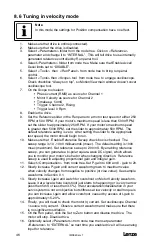
Страница 46: ...s 12 From Node menu choose Connect Drive 13 Click Connect one button type 1 in the address box and press OK to dismiss dialog 14 Drive connects and its icon appears in the left node tree of the MotionView s screen Note You only have to set up properties the first time or whenever you change the port Refer to MotionView User s Manual for details how to make a connection to the drive 15 Double click ...

Страница 47: ...ppr after quadrature Problem Setup drive so motor can follow master encoder wheel with gear ratio N 1 3 Motor Encoder Encoder Wheel 4000 1000 4 Master to System ratio 4000 1000 1 3 4000 1 1000 3 4 3 8 4 Dual loop feedback In dual loop operation position mode only to establish relationship between Master input and mechanical system movement two parameters need to be set First parameter Master to sy...

Страница 48: ...o run 10 Make sure that Enable Reference Sweep check box is checked The sweep range is 10 1000 milliseconds msec The default setting is 1000 msec maximum Set reference sweep to 200 mS By enabling reference sweep you can generate a bi polar square wave DC signal which allows you to monitor your motor s behavior when changing direction Reference sweep is used in adjusting proportional gain and integ...

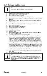
Страница 49: ...ain and watch for Position error waveform Continue to increase both gains until you see noticeable oscillation on flat portion of waveform Now stop increasing P gain and continue to increase D gain until oscillation stops Now the ratio between P gain and D gain is set and if you need to increase or decrease P gain in next steps you will need also increase decrease D gain accordingly to keep their r...

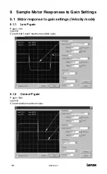
Страница 50: ...r Responses to Gain Settings 9 1 Motor response to gain settings Velocity mode 9 1 1 Low P gain P gain 100 I gain 0 Current didn t reach maximum possible value 9 1 2 Correct P gain P gain 500 I gain 0 Current reaches maximum value ...

Страница 51: ...mv1 l 49 9 1 3 I gain too high P gain 500 I gain 300 Notice big velocity overshoot 9 1 4 Correct P gain and I gain P gain 500 I gain 100 Notice very low velocity overshoot and very close match of the waveforms ...

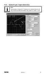
Страница 52: ...elationship P gain 200 D gain 300 Problem Noticeable oscillation Channel 2 Insufficient D gain excess of P gain for this D gain setting Treatment Decrease P gain increase D gain Side effects Decreasing P gain increases position error Increasing D gain lowers bandwidth and increases hi frequency noise ...

Страница 53: ...IMS94S mv1 l 51 9 2 2 Optimal P gain D gain relationship Note Fixed problem in Section 9 2 Position error is small and only 20 mS long Position regulation bandwidth of the system is 1 20mS 50Hz ...

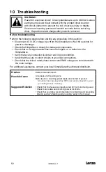
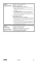
Страница 54: ...ial has become lodged on or fallen into the SimpleServo Verify that every connection is correct and in good condition Verify that there are no short circuits or grounded connections Check that the drive s rated phase current and RMS voltage are consistent with the motor ratings For additional assistance contact your local SimpleServo authorized distributor Problem External line fuse blows Possible...

Страница 55: ...t run at all In step and direction mode Step and Direction inputs are not wired correctly In MotionView program check Parameters Step input type is set for S D if you use a step and direction indexer output and Master Encoder if you use quadrature type output from a master motor encoder or indexer Position loop P gain set to 0 Set P gain to 100 and D gain to 200 If in PIVFF mode or if in P V mode ...

Страница 56: ...l IMS94S mv1 54 ...

Страница 57: ...IMS94S mv1 l 55 ...

Страница 58: ...l IMS94S mv1 56 ...

Страница 59: ...IMS94S mv1 l 57 ...

Страница 60: ...l IMS94S mv1 58 ...

Страница 61: ...IMS94S mv1 l 59 ...

Страница 62: ...l IMS94S mv1 60 ...

Страница 63: ...IMS94S mv1 l 61 ...

Страница 64: ...l IMS94S mv1 62 ...

Страница 65: ...IMS94S mv1 l 63 ...

Страница 66: ...AC Technology Corporation member of the Lenze Group 630 Douglas Street Uxbridge MA 01569 Telephone 508 278 9100 Facsimile 508 278 7873 ...

Отзывы: