l
IMS94S-mv1
44
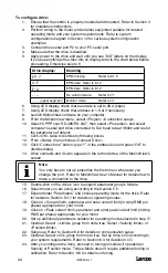
To configure drive:
1. Ensure that the control is properly installed and mounted. Refer to Section 4
for installation instructions.
2. Perform wiring to the motor and external equipment suitable for desired
operating mode and your system requirements. Refer to system
configurations diagram in Section 12 for various system configuration
examples.
3. Connect drive serial port P2 to your PC serial port.
4. Make sure that the drive is disabled.
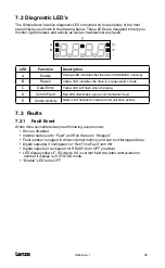
5. Apply power to the drive and wait until you see “DiS” letters on the display.
If you see anything other then this on display refer to the chart below before
proceeding. Otherwise skip to 6
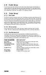
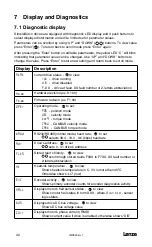
Drive display:
Meaning
EP ?
EPM missing.
Refer to 6.1.2
d-E
EPM data Refer to 6.1.2
E-d
EPM data Refer to 6.1.2
- - - -
No valid firmware
Refer to 7.1
- - - - (upper segment)
Monitor mode
Refer to 7.1
6. Using LED display check that baud rate is set to 38.4 (kbps).
7. Using LED display check that address is 1. Set if necessary.
8. Launch MotionView software on your computer.
9. From the MotionView menu, select <Project> <Connection setup>.
10. Select “UPPP over RS-485/RS-232”, then select <Properties> and select
computer’s serial port drive connected to. Set baud rate at 38400 and rest of
the parameters at default.
11. Click <OK> twice to dismiss both dialog boxes.
12. From <Node> menu choose <Connect Drive>.
13. Click “Connect one” button, type “1” in the address box and press “OK” to
dismiss dialog.
14. Drive connects and its icon appears in the left node tree of the MotionView’s
screen.
Note
You only have to set up properties the first time or whenever you
change the port. Refer to MotionView User’s Manual for details how to
make a connection to the drive.
15. Double-click on the drive’s icon to expand parameter group’s folders.
16. Select motor you are using according to the Section 5.5.
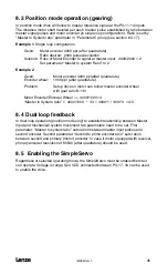
17. Expand folder “Parameters” and choose operating mode for the drive. Refer
for details to Section 6.3.1 for details on operating modes.
18. Click on <Current limit> parameter and enter current limit (in Amp RMS per
phase) appropriate for your motor.
19. Click on <Peak current limit> parameter and enter peak current limit (in Amp
RMS per phase) appropriate for your motor.
20. Set up additional parameters suitable for operating mode selected in step 17.
21. Optional. Select <Limits> group from node tree. Select <Velocity limits> or
<Position limits>.
22. Subgroup. Refer to Section 6.9 for details on compensation setup.
23. Optional. Select <I/O> group from node tree. Set up drive’s I/O according to
your system requirements. Refer to Section 6.4 for details on I/O.
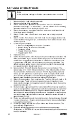
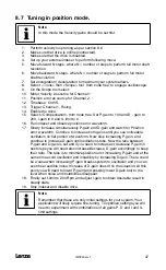
24. After you configure the drive, proceed to tuning procedure if operating in
Velocity or Position mode. Torque Mode doesn’t require additional tuning or
calibration. Refer to Section 8.6 for details on tuning.
Содержание SimpleServo 94
Страница 1: ...MODEL 94 USERS MANUAL IMS94S mv1 ...
Страница 12: ...l IMS94S mv1 10 3 2 Clearance for Cooling Air Circulation ...
Страница 56: ...l IMS94S mv1 54 ...
Страница 57: ...IMS94S mv1 l 55 ...
Страница 58: ...l IMS94S mv1 56 ...
Страница 59: ...IMS94S mv1 l 57 ...
Страница 60: ...l IMS94S mv1 58 ...
Страница 61: ...IMS94S mv1 l 59 ...
Страница 62: ...l IMS94S mv1 60 ...
Страница 63: ...IMS94S mv1 l 61 ...
Страница 64: ...l IMS94S mv1 62 ...
Страница 65: ...IMS94S mv1 l 63 ...


