l
IMS94S-mv1
46
8.6 Tuning in velocity mode
Note
In this mode the settings for Position compensation have no effect.
1. Make sure that drive is online (connected).
2. Make sure that the drive is disabled.
3. Select <Parameters> folder from the node tree. Click on <Reference>
parameter and change it to “INTERNAL”. This will tell drive to use internally
generated reference controlled by Run panel tool.
4. Select <Parameters> folder from node tree. Make sure that Enable Accel/
Decel limits set to “DISABLE”.
5. Select <Tools> then <Run Panel > from node tree to bring run panel
control.
6. Select <Tools> then <Scope> tool from node tree to engage oscilloscope.
Check checkbox “Always on top”, so MotionView main window doesn’t cover
oscilloscope tool.
7. On the Scope tool select:
• Phase current (RMS) as source for Channel 1
• Motor Velocity as source for Channel 2
• Timebase: 50mS
• Trigger: Channel 2, Rising
• Trigger level 0 Rpm
8. Enable the drive.
9. Set the Reference slider in the Run panel to a motor test speed of either 250
RPM or 500 RPM. If your motor’s maximum speed is less than 5000 RPM,
set the slider to approximately 250 RPM. If your motor’s maximum speed
is greater than 5000 RPM, set the slider to approximately 500 RPM. The
default reference setting is zero. After setting the slider to the appropriate
test speed, the motor should begin to run.
10. Make sure that Enable Reference Sweep check box is checked. The
sweep range is 10 - 1000 milliseconds (msec). The default setting is 1000
msec (maximum). Set reference sweep to 200 mS. By enabling reference
sweep, you can generate a bi-polar square-wave DC signal, which allows
you to monitor your motor’s behavior when changing direction. Reference
sweep is used in adjusting proportional gain and integral gain.
11. Select <Compensation> from node tree. Set P-gain to 600 and I - gain to 20.
12. Slowly increase P-gain until current waveform grows to maximum value
when velocity changes from negative to positive (or visa versa). See sample
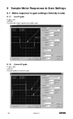
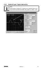
waveforms in Section 9.1.
13. Slowly increase I-gain and watch for overshoot on Motor Velocity waveform.
Leave it at a level where overshoot just starts to happening or is very narrow
(less then 5mS or less then 3-5%). If fast acceleration/deceleration in your
servo system is not an objective but stiffness at low velocity or stall torque is
you can increase I-gain and allow overshoot caused by excess of I-gain to
approximately 15-20%.
14. Finally, you will need to check the motor Iq current. Set oscilloscope Channel
1 source to Iq current. Observe current waveform and make sure that there
is no significant oscillation.
15. On the Run panel, click the Set to Zero button and disable the drive. The
motor will stop. Disable drive.
16. Optionally select <Parameters> from node tree then set parameter
<Reference> to “EXTERNAL” so next time you enable drive it will use analog
input for reference.
Содержание SimpleServo 94
Страница 1: ...MODEL 94 USERS MANUAL IMS94S mv1 ...
Страница 12: ...l IMS94S mv1 10 3 2 Clearance for Cooling Air Circulation ...
Страница 56: ...l IMS94S mv1 54 ...
Страница 57: ...IMS94S mv1 l 55 ...
Страница 58: ...l IMS94S mv1 56 ...
Страница 59: ...IMS94S mv1 l 57 ...
Страница 60: ...l IMS94S mv1 58 ...
Страница 61: ...IMS94S mv1 l 59 ...
Страница 62: ...l IMS94S mv1 60 ...
Страница 63: ...IMS94S mv1 l 61 ...
Страница 64: ...l IMS94S mv1 62 ...
Страница 65: ...IMS94S mv1 l 63 ...


