IMS94S-mv1
l
21
���������
��������
���������
��������
���
�
���
�
����
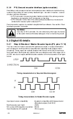
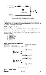
Master encoder/step and direction input circuit.
You can connect a single ended or differential signal to the inputs. You can also
connect sinking or sourcing outputs to these inputs. The function of these inputs
“Master Encoder” or “Step and Direction” is software selectable. Use MotionView set
up program to choose desirable function.
5.2.2 Digital outputs
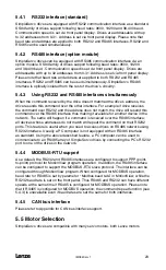
There are two digital outputs (“OUT1” and “OUT2”) available on P3. Outputs are
fully isolated from the rest of the drive circuits (“dry contacts”). See figure below
for its electrical diagram. Output polarity is programmable i.e. each output can be
programmed for N.O. or N.C. operation. Each output can be assigned to one of the
following functions:
• Zero speed
• In-speed window
• Current limit
• Run-time fault
• Ready
• Brake release
Digital outputs electrical characteristics
Circuit type
Isolated Open Collector
Digital outputs load capability
10mA
Digital outputs Collector-Emitter max voltage
30V
������
������
������
������
��
��
��
��
Digital outputs circuit.
5.2.3 Digital inputs
Содержание SimpleServo 94
Страница 1: ...MODEL 94 USERS MANUAL IMS94S mv1 ...
Страница 12: ...l IMS94S mv1 10 3 2 Clearance for Cooling Air Circulation ...
Страница 56: ...l IMS94S mv1 54 ...
Страница 57: ...IMS94S mv1 l 55 ...
Страница 58: ...l IMS94S mv1 56 ...
Страница 59: ...IMS94S mv1 l 57 ...
Страница 60: ...l IMS94S mv1 58 ...
Страница 61: ...IMS94S mv1 l 59 ...
Страница 62: ...l IMS94S mv1 60 ...
Страница 63: ...IMS94S mv1 l 61 ...
Страница 64: ...l IMS94S mv1 62 ...
Страница 65: ...IMS94S mv1 l 63 ...


