


l
IMS94S-mv1
14
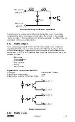
5 SimpleServo Connections
The standard SimpleServo control contains seven connectors: four quick-connect
terminal blocks and three subminiature type “D” connectors. These connectors provide
power, communications and external feedback to the motor, SimpleServo control,
and host controller (Figure 8). Prefabricated cable assemblies may be purchased
from Lenze to facilitate wiring the control, motor and host computer. Contact your
SimpleServo Sales Representative for assistance.
5.1 External Connectors
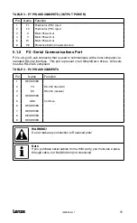
5.1.1 P1 & P7 - Input Power and Output Power Connections
P1 is a 3 or 4-pin quick-connect terminal block used for input (mains) power. P7 is a
6-pin quick-connect terminal block used for output power to the motor. P7 also has
a thermistor (PTC) input for motor over-temperature protection. Refer to Tables 3
and 4 for connector pin assignments. Where referenced in the table below, refer to
Connector Wiring Notes for more information.
WARNING!
• Hazard of electrical shock! Circuit potentials are up to 480 VAC
above earth ground. Avoid direct contact with the printed circuit
board or with circuit elements to prevent the risk of serious injury
or fatality. Disconnect incoming power and wait 60 seconds before
servicing drive. Capacitors retain charge after power is removed.
• DO NOT connect incoming power to the output motor terminals
(U, V, W)! Severe damage to the SimpleServo will result..
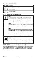
All conductors must be enclosed in one shield and jacket around them. The shield
on the amplifier end must be terminated at P1 pin 4 (chassis ground); the other end
should be properly terminated at the motor shield. To satisfy CE requirements, Lenze
recommends that you purchase SimpleServo cables for both the motor and AC line.
Contact your SimpleServo representative for assistance.
Wire size
I < 8 A:
16 AWG (1.5 mm
2
) or 14 AWG (2.5 mm
2
)
8 A < I < 12 A 14 AWG (2.5 mm
2
) or 12 AWG (4.0 mm
2
)
I > 12 A:
12 AWG (4.0 mm
2
)
TABLE 2 - P1 PIN ASSIGNMENTS (INPUT POWER)
Standard Models
Doubler Models
Pin Name Function
Name Function
1
PE
Protective Earth (Ground)
PE
Protective Earth (Ground)
2
L1
AC Power in
N
AC Power Neutral
(120V Doubler only)
3
L2
AC Power in
L1
AC Power in
4
L3
AC Power in
(3~ models only)
L2/N
AC Power in
(non-doubler operation)
Содержание SimpleServo 94
Страница 1: ...MODEL 94 USERS MANUAL IMS94S mv1 ...
Страница 12: ...l IMS94S mv1 10 3 2 Clearance for Cooling Air Circulation ...
Страница 56: ...l IMS94S mv1 54 ...
Страница 57: ...IMS94S mv1 l 55 ...
Страница 58: ...l IMS94S mv1 56 ...
Страница 59: ...IMS94S mv1 l 57 ...
Страница 60: ...l IMS94S mv1 58 ...
Страница 61: ...IMS94S mv1 l 59 ...
Страница 62: ...l IMS94S mv1 60 ...
Страница 63: ...IMS94S mv1 l 61 ...
Страница 64: ...l IMS94S mv1 62 ...
Страница 65: ...IMS94S mv1 l 63 ...


