Internal LEDs, connectors, and jumpers
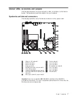
The following illustrations show the connectors, LEDs, and jumpers on the internal
boards. The illustrations might differ slightly from your hardware.
System-board internal connectors
The following illustration shows the internal connectors on the system board.
1
Wake on LAN connector
10
Power connector
2
SATA 2 connector
11
Fan 5 connector
3
SATA 0 connector
12
Fan 4 connector
4
Power connector
13
Microprocessor connector
5
SAS/SATA controller card connector
14
Fan 3 connector
6
Front USB connector
15
Fan 2 connector
7
Operator information panel connector
16
Fan 1 connector
8
Hot-swap SAS/SATA backplane power
connector
17
IDE connector
9
SAS signal connector (some models)
Important:
Use only a supported IBM SAS/SATA controller in the SAS/SATA
controller card connector. For a list of supported optional devices for the server, see
http://www.lenovo.com/accessories.
Chapter 1. Introduction
7
Содержание ThinkServer RS110
Страница 1: ...ThinkServer RS110 Types 6435 6436 6437 and 6438 Hardware Maintenance Manual ...
Страница 2: ......
Страница 3: ...ThinkServer RS110 Types 6435 6436 6437 and 6438 Hardware Maintenance Manual ...
Страница 8: ...vi ThinkServer RS110 Types 6435 6436 6437 and 6438 Hardware Maintenance Manual ...
Страница 18: ...xvi ThinkServer RS110 Types 6435 6436 6437 and 6438 Hardware Maintenance Manual ...
Страница 74: ...56 ThinkServer RS110 Types 6435 6436 6437 and 6438 Hardware Maintenance Manual ...
Страница 238: ...220 ThinkServer RS110 Types 6435 6436 6437 and 6438 Hardware Maintenance Manual ...
Страница 251: ......
Страница 252: ...Part Number 46U0856 Printed in USA 1P P N 46U0856 ...

