background image

• If an adapter or a device consists of more than one FRU, any of the FRUs may be the cause of the error.

Before replacing the adapter or device, remove the FRUs, one by one, to see if the symptoms change.
Replace only the FRU that changed the symptoms.

Attention:

The setup configuration on the computer you are servicing may have been customized. Running

Automatic Configuration may alter the settings. Note the current configuration settings (using the View
Configuration option); then, when service has been completed, verify that those settings remain in effect.

Strategy for replacing a hard disk drive

Always try to run a low-level format before replacing a hard disk drive. This will cause all customer data on
the hard disk to be lost. Be sure that the customer has a current backup of the data before doing this task.

Attention:

The drive startup sequence in the computer you are servicing may have been changed. Be

extremely careful during write operations such as copying, saving, or formatting. If you select an incorrect
drive, data or programs can be overwritten.

Important notice for replacing a system board

Some components mounted on a system board are very sensitive. Improper handling of a system board can
cause damage to those components, and may cause a system malfunction.

Attention:

When handling a system board:

• Do not drop a system board or apply any excessive force to it.

• Avoid rough handling of any kind.

• Avoid bending a system board and hard pushing to prevent cracking at each BGA (Ball Grid Array) chipset.

How to use error message

Use the error codes displayed on the screen to diagnose failures. If more than one error code is displayed,
begin the diagnosis with the first error code. Whatever causes the first error code may also cause false error
codes. If no error code is displayed, see whether the error symptom is listed in the Symptom-to-FRU
Index for the computer you are servicing.

Strategy for replacing FRUs for CTO, CMV, and GAV

Product definition

Dynamic Configure To Order (CTO)

This provides the ability for a customer to configure an IBM

®

or a Lenovo solution from an eSite, and have

this configuration sent to fulfillment, where it is built and shipped directly to the customer. The machine
label, Product Entitlement Warehouse (PEW), eSupport, and the HMM will load these products as the 4-digit
MT and 3-digit model, where model = “CTO” (Example: 1829-CTO).

Custom Model Variant (CMV)

This is a unique configuration that has been negotiated between IBM or Lenovo and the customer. A unique
4-digit MT and 3-digit model is provided to the customer to place orders (Example: 1829-W15). A CMV
is a special bid offering. Therefore, it is NOT generally announced.

• The MTM portion of the machine label is the 4-digit MT and 3-digit model, where model = “CTO”

(Example: 1829-CTO). The PRODUCT ID portion of the machine label is the 4-digit MT and 3-digit CMV
model (Example: 1829-W15).

24

Hardware Maintenance Manual

Содержание 440128U

Страница 1: ...Hardware Maintenance Manual ThinkPad Edge E420s ...

Страница 2: ...tion under Notices on page 97 First Edition March 2011 Copyright Lenovo 2011 LIMITED AND RESTRICTED RIGHTS NOTICE If data or software are delivered pursuant a General Services Administration GSA contract use reproduction or disclosure is subject to restrictions set forth in Contract No GS 35F 05925 ...

Страница 3: ...rd 36 Supervisor password 37 How to remove the power on password 37 How to remove the hard disk password 37 Power management 38 Screen blank mode 38 Sleep standby mode 38 Hibernation mode 39 Symptom to FRU index 39 Numeric error codes 40 Error messages 40 No beep symptoms 41 LCD related symptoms 41 Intermittent problems 41 Undetermined problems 42 Chapter 5 Status indicators 43 Chapter 6 Special k...

Страница 4: ...LCD FRUs 87 Keyboard 89 Miscellaneous parts 90 AC power adapters 90 Power cords 91 Recovery discs 92 Windows XP Professional DVDs 92 Windows 7 Home Basic 32 bit DVDs 93 Windows 7 Home Premium 32 bit DVDs 93 Windows 7 Home Premium 64 bit DVDs 93 Windows 7 Professional 32 bit DVDs 94 Windows 7 Professional 64 bit DVDs 95 Windows 7 Ultimate 64 bit DVDs 95 Common service tools 96 Notices 97 Electronic...

Страница 5: ...eshoot problems Important This manual is intended only for trained service technicians who are familiar with ThinkPad products Use this manual along with the advanced diagnostic tests to troubleshoot problems effectively Before servicing a ThinkPad product be sure to read all the information under Chapter 1 Safety information on page 1 and Chapter 2 Important service information on page 23 Copyrig...

Страница 6: ...iv Hardware Maintenance Manual ...

Страница 7: ...t unsafe Before you start the machine make sure that other service technicians and the customer s personnel are not in a hazardous position Place removed covers and other parts in a safe place away from all personnel while you are servicing the machine Keep your toolcase away from walk areas so that other people will not trip over it Do not wear loose clothing that can be trapped in the moving par...

Страница 8: ...ent keep the other hand in your pocket or behind your back Attention An electrical shock can occur only when there is a complete circuit By observing the above rule you may prevent a current from passing through your body When using testers set the controls correctly and use the approved probe leads and accessories for that tester Stand on suitable rubber mats obtained locally if necessary to insu...

Страница 9: ...eck exterior covers for damage loose broken or sharp edges 2 Power off the computer Disconnect the power cord 3 Check the power cord for a A third wire ground connector in good condition Use a meter to measure third wire ground continuity for 0 1 ohm or less between the external ground pin and the frame ground b The power cord should be the type specified in the parts list c Insulation must not be...

Страница 10: ...ce requirement Note The use of a grounding system to guard against ESD damage is desirable but not necessary Attach the ESD ground clip to any frame ground ground braid or green wire ground When working on a double insulated or battery operated system use an ESD common ground or reference point You can use coax or connector outside shells on these systems Use the round ground prong of the ac plug ...

Страница 11: ...DANGER DANGER DANGER DANGER DANGER Chapter 1 Safety information 5 ...

Страница 12: ...DANGER 6 Hardware Maintenance Manual ...

Страница 13: ...PERIGO PERIGO PERIGO Chapter 1 Safety information 7 ...

Страница 14: ...PERIGO PERIGO PERIGO PERIGO PERIGO DANGER 8 Hardware Maintenance Manual ...

Страница 15: ...DANGER DANGER DANGER DANGER DANGER Chapter 1 Safety information 9 ...

Страница 16: ...DANGER DANGER VORSICHT VORSICHT VORSICHT 10 Hardware Maintenance Manual ...

Страница 17: ...VORSICHT VORSICHT VORSICHT VORSICHT VORSICHT Chapter 1 Safety information 11 ...

Страница 18: ...12 Hardware Maintenance Manual ...

Страница 19: ...Chapter 1 Safety information 13 ...

Страница 20: ...14 Hardware Maintenance Manual ...

Страница 21: ...Chapter 1 Safety information 15 ...

Страница 22: ...16 Hardware Maintenance Manual ...

Страница 23: ...ual translations The laser compliance statements in this section are provided in the following languages English Arabic Brazilian Portuguese French German Hebrew Japanese Korean Spanish Traditional Chinese Chapter 1 Safety information 17 ...

Страница 24: ...18 Hardware Maintenance Manual ...

Страница 25: ...Chapter 1 Safety information 19 ...

Страница 26: ...20 Hardware Maintenance Manual ...

Страница 27: ...Chapter 1 Safety information 21 ...

Страница 28: ...22 Hardware Maintenance Manual ...

Страница 29: ...g or installing any software fixes drivers and UEFI BIOS downloads Customers in Canada should call the Customer Support Center at 800 565 3344 for assistance or download information Strategy for replacing FRUs Before replacing parts Make sure that all software fixes drivers and UEFI BIOS downloads are installed before replacing any FRUs listed in this manual After a system board is replaced ensure...

Страница 30: ...pply any excessive force to it Avoid rough handling of any kind Avoid bending a system board and hard pushing to prevent cracking at each BGA Ball Grid Array chipset How to use error message Use the error codes displayed on the screen to diagnose failures If more than one error code is displayed begin the diagnosis with the first error code Whatever causes the first error code may also cause false...

Страница 31: ...umber not CTO Example 1829 F1U PEW can be accessed at the following Web site http www lenovo com support site wss document do lndocid LOOK WARNTY Select Warranty lookup Input the MT and the Serial number and the list of key commodities will be returned in the PEW record under COMPONENT INFORMATION Using eSupport For Key Commodities Examples hard disk drive system board microprocessor LCD and memor...

Страница 32: ...26 Hardware Maintenance Manual ...

Страница 33: ...ariety of reasons that have nothing to do with a hardware defect such as cosmic radiation electrostatic discharge or software errors Consider replacing a FRU only when a problem recurs If you suspect that a FRU is defective clear the error log and run the test again If the error does not recur do not replace the FRU Be careful not to replace a nondefective FRU What to do first When you do return a...

Страница 34: ...ook Note The diagnostic tests are intended to test only ThinkPad products The use of non ThinkPad products prototype cards or modified options can lead to false indications of errors and invalid system responses 1 Identify the failing symptoms in as much detail as possible 2 Verify the symptoms Try to re create the failure by running the diagnostic test or by repeating the operation Diagnostics us...

Страница 35: ...r sources If an error code appears go to Symptom to FRU index on page 39 4 When the ThinkPad logo comes up immediately press F12 to enter the Network Boot menu 5 Insert the PC Doctor CD into the internal optical drive 6 Press cursor keys to select ATAPI CDx x 0 1 and then press Enter 7 Follow the instructions on the screen 8 The main panel of PC Doctor appears 9 Select Diagnostics with the arrow k...

Страница 36: ...PC Doctor shows messages describing it 12 To exit the test select Quit Exit Diag To cancel the test press Esc Note After running PC Doctor check the time and date on the system and reset them if they are incorrect Detecting system information with PC Doctor PC Doctor can detect the following system information Hardware Info System Configuration Memory Contents Physical Disk Drives VGA Information ...

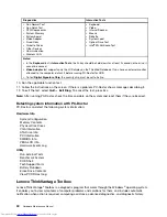
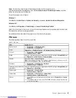
Страница 37: ... Devices AC Adapter Battery 1 Battery2 LCD unit 1 Diagnostics Video Adapter 2 Interactive Tests Video Audio Enter the ThinkPad Setup and change Serial ATA SATA setting to Compatibility and run Diagnostics Other Device Conexant Audio Speaker Interactive Tests Internal Speaker Note Once Audio test is done the no sound is heard this test In this case turn off and turn on the computer Then run this te...

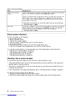
Страница 38: ...he ac power adapter 4 Check that power is supplied when you turn on the computer 5 Turn off the computer 6 Disconnect the ac power adapter and install the charged battery pack 7 Check that the battery pack supplies power when you turn on the computer If you suspect a power problem see the appropriate one of the following power supply checkouts Checking the ac power adapter on page 32 Checking oper...

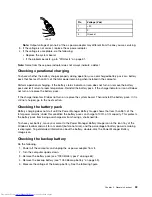
Страница 39: ...ill does not turn on replace the system board Then reinstall the battery pack If it is still not charged go to the next section Checking the battery pack Battery charging does not start until the Power Manager Battery Gauge shows that less than 96 of the total power remains under this condition the battery pack can charge to 100 of its capacity This protects the battery pack from being overcharged...

Страница 40: ... Ground Red Black If the voltage is correct replace the system board If the voltage is not correct replace the backup battery If the backup battery discharges quickly after replacement replace the system board 34 Hardware Maintenance Manual ...

Страница 41: ...disc to start the recovery process Applications and Drivers Recovery Disc one or more discs This disc restores the preinstalled applications and drivers on the computer Supplemental Recovery Disc This disc contains additional content such as updates to the software that was preinstalled on the computer Not all recovery disc sets come with a Supplemental Recovery Disc Notes You must have a DVD driv...

Страница 42: ...es at a time This is normal 10 When the recovery process is complete the Set Up Windows screen is displayed Follow the instructions on the screen to complete the Windows setup 11 After you have completed the Windows setup you might want to restore the original startup sequence Start the ThinkPad Setup and then press F9 to restore the default settings Press F10 to save and exit the ThinkPad Setup N...

Страница 43: ...ff the computer 2 Remove the battery pack For how to remove the battery pack see 1090 Battery pack on page 62 3 Remove the backup battery For how to remove the backup battery see 1050 Backup battery on page 59 4 Turn on the computer and wait until the POST ends After the POST ends the password prompt does not appear The POP has been removed 5 Reinstall the backup battery and the battery pack B If ...

Страница 44: ... sleep standby mode the following events occur in addition to what occurs in screen blank mode The LCD is powered off The hard disk drive is powered off The CPU stops To enter sleep standby mode press F4 Note You can change the action of the F4 key combination by changing the settings in Power Manager In certain circumstances the computer goes into sleep standby mode automatically If a suspend tim...

Страница 45: ...s been set on the timer and if the user does not do any operation with the keyboard the TrackPoint the hard disk drive the parallel connector or the diskette drive within that time If the timer conditions are satisfied in suspend mode When the power is turned on the computer returns from hibernation mode and resumes operation The hibernation file in the boot record on the hard disk drive is read a...

Страница 46: ...hort beeps 1 Charge the battery pack 2 Battery pack 0191 System Security Invalid Remote Change requested 1 Run ThinkPad Setup and then save current setting by pressing F10 2 System board 0251 System CMOS checksum bad Default configuration used two short beeps 1 Charge the backup battery for more than 8 hours by connecting the ac power adapter 2 Replace the backup battery and run ThinkPad Setup to ...

Страница 47: ...Lenovo and it should be replaced Notes This policy applies to all ThinkPad Notebooks purchased on 1 January 2008 or later Lenovo will not provide replacement if the LCD is within specification as we cannot guarantee that any replacement LCD will have zero pixel defects One pixel consists of R G B sub pixels Table 5 LCD related symptoms Symptom or error FRU or action in sequence No beep power on in...

Страница 48: ...er supply being used at the time of the failure is operating correctly See Power system checkout on page 32 1 Turn off the computer 2 Visually check each FRU for damage Replace any damaged FRU 3 Remove or disconnect all of the following devices a Non ThinkPad devices b Printer mouse and other external devices c Battery pack d Hard disk drive e External diskette drive or optical drive f DIMM g Opti...

Страница 49: ... You can enter all alphabetic characters A Z in uppercase without pressing the Shift key Wireless status Press F9 to enable or disable the wireless features You can quickly change the power state of each feature in the list 3 Power status Green The ac power adapter is connected If a battery is installed on the computer it is charged when this indicator is on Off The ac power adapter is not connect...

Страница 50: ... on the palm rest works as a system status indicator it shows whether the computer is in sleep standby hibernation or normal model Red The computer is on in normal mode Fast blinking red The computer is entering sleep standby or hibernation mode Slow blinking red The computer is in sleep standby mode Off The computer is off or in hibernation mode 44 Hardware Maintenance Manual ...

Страница 51: ...nd the audio streaming will continue Switching a display output location F6 For Windows 7 Switch between the computer display and an external monitor Windows will show these display options Computer display only LCD Computer display and external monitor same image Computer display and external monitor extended desktop function External monitor only Note To switch between the computer display and a...

Страница 52: ...ou can quickly change the power state of each feature in the list Notes If you want to use this button to enable or disable the wireless features the following device drivers must be installed on your computer beforehand Power Management driver OnScreen Display Utility Wireless device drivers Previous track scene F10 Play pause F11 Next track scene F12 For Multimedia control 46 Hardware Maintenanc...

Страница 53: ...laneous parts on page 90 in your tool bag Always use new screws Use a torque screwdriver if you have one Tighten screws as follows Plastic to plastic Turn an additional 90 degrees after the screw head touches the surface of the plastic part Logic card to plastic Turn an additional 180 degrees after the screw head touches the surface of the logic card Torque driver If you have a torque driver refer...

Страница 54: ...uter is displayed the serial number of the system unit is listed as follows 20 Serial number Write down that number Note The serial number of the system unit is also written on the label attached to the bottom of the computer After you have replaced the system board restore the serial number by doing the following 1 Install the LENOVO ThinkPad Hardware Maintenance Diskette Version 1 76 or later an...

Страница 55: ...estart the computer 2 From the main menu select 6 Set ECA Information 3 To read ECA information select 2 Read ECA rework number from EEPROM and follow the instruction 4 To read box build date select 5 Read box build date from EEPROM and follow the instruction on the screen After an ECA has been applied to the machine the EEPROM must be updated to reflect the ECA s application Use the LENOVO ThinkP...

Страница 56: ...50 Hardware Maintenance Manual ...

Страница 57: ...and arranging internal cables see Chapter 9 Locations on page 81 8 When replacing a FRU use the correct screw s as shown in the procedures DANGER Before removing any FRU turn off the computer unplug all power cords from electrical outlets remove the battery pack and then disconnect any interconnecting cables Attention After replacing a FRU do not turn on the computer until you have made sure that ...

Страница 58: ...1 2 1010 ExpressCard blank bezel and Media Card blank bezel Table 8 Removal steps of ExpressCard blank bezel When you press the ExpressCard blank bezel 1 it pops out 2 1 2 52 Hardware Maintenance Manual ...

Страница 59: ...ntinued When installing Make sure that the bezel is correctly oriented as shown in the following figure 3 Table 9 Removal steps of Media Card blank bezel When you press the Media Card blank bezel 1 it pops out 2 Chapter 8 Removing and replacing a FRU 53 ...

Страница 60: ...drive or apply any physical shock to it The drive is sensitive to physical shock Improper handling can cause damage and permanent loss of data Before removing the drive have the user make a backup copy of all the information on it if possible Never remove the drive while the computer is operating or is in suspend mode Table 10 Removal steps of HDD or SSD assembly 1 2 Step Screw quantity Color Torq...

Страница 61: ...181 Nm 1 85 kgfcm Table 11 Removal steps of HDD or SSD bracket 1 1 1 1 2 Step Screw quantity Color Torque 1 M2 4 mm flat head nylon coated 4 Black 0 181 Nm 1 85 kgfcm 1030 Keyboard For access remove 1020 Hard disk drive or solid state drive assembly on page 54 Chapter 8 Removing and replacing a FRU 55 ...

Страница 62: ...Table 12 Removal steps of keyboard 1 1 Step Screw quantity Color Torque 1 M2 3 mm wafer head nylon coated 2 Black 0 181 Nm 1 85 kgfcm 2 2 56 Hardware Maintenance Manual ...

Страница 63: ...Table 12 Removal steps of keyboard continued 3 3 4 8 7 5 6 Chapter 8 Removing and replacing a FRU 57 ...

Страница 64: ...following figure 3 Secure the keyboard by tightening the screws from the bottom side of the computer 1040 Top case assembly For access remove 1020 Hard disk drive or solid state drive assembly on page 54 Table 14 Removal steps of top case assembly 1 1 1 1 1 1 1 1 1 Step Screw quantity Color Torque 1 M2 3 mm wafer head nylon coated 8 Black 0 181 Nm 1 85 kgfcm 58 Hardware Maintenance Manual ...

Страница 65: ...d 2 3 4 5 6 8 7 9 10 11 12 12 12 1050 Backup battery For access remove these FRUs in order 1020 Hard disk drive or solid state drive assembly on page 54 1030 Keyboard on page 55 1040 Top case assembly on page 58 Chapter 8 Removing and replacing a FRU 59 ...

Страница 66: ...onnector is attached firmly 1060 Speaker assembly For access remove these FRUs in order 1020 Hard disk drive or solid state drive assembly on page 54 1030 Keyboard on page 55 1040 Top case assembly on page 58 1090 Battery pack on page 62 Table 16 Removal steps of speaker assembly 1 1 1 1 1 1 1 1 2 2 When installing Make sure that the connector is attached firmly 60 Hardware Maintenance Manual ...

Страница 67: ...0 Top case assembly on page 58 Table 17 Removal steps of fingerprint reader 1 2 3 4 When installing Make sure that the connector is attached firmly 1080 Touch pad 1080 Touch pad For access remove these FRUs in order 1020 Hard disk drive or solid state drive assembly on page 54 1030 Keyboard on page 55 1040 Top case assembly on page 58 Chapter 8 Removing and replacing a FRU 61 ...

Страница 68: ...ack is defective A battery pack FRU should not be replaced unless this diagnostic shows that the battery is defective The only exception to this is if the battery pack is physically damaged or a customer is reporting a possible safety issue If Lenovo ThinkVantage Toolbox is not installed in the computer the customer should download this program before a non physically damaged battery pack is repla...

Страница 69: ...y connector 2 1 2 1100 Optical drive or travel cover For access remove these FRUs in order 1020 Hard disk drive or solid state drive assembly on page 54 1030 Keyboard on page 55 1040 Top case assembly on page 58 1090 Battery pack on page 62 1180 LCD unit on page 73 Table 20 Removal steps of optical drive or travel cover 1 1 Step Screw quantity Color Torque Chapter 8 Removing and replacing a FRU 63...

Страница 70: ...o the socket Press the DIMM in firmly and pivot it until it snaps into place Make sure that it is firmly fixed in the slot and does not move easily For access remove these FRUs in order 1020 Hard disk drive or solid state drive assembly on page 54 1030 Keyboard on page 55 1120 PCI Express Mini Card for wireless LAN on page 65 1130 PCI Express Mini Card for wireless WAN on page 67 1040 Top case ass...

Страница 71: ...IMM in firmly and pivot it until it snaps into place Make sure that it is firmly fixed in the slot and does not move easily 1120 PCI Express Mini Card for wireless LAN For access remove 1030 Keyboard on page 55 Table 23 Removal steps of PCI Express Mini Card for wireless LAN Remove the screws 1 Then remove the antenna RF connectors 2 Note Some models might have a third white antenna cable Chapter ...

Страница 72: ...talling Plug the gray cable into the jack marked MAIN or M and the black cable into the jack marked AUX or A on the card Note In models with a wireless LAN card that has three antenna connectors plug the gray cable MAIN into the jack marked TR1 the white cable third into the jack marked RO or TR3 and the black cable AUX into the jack marked TR2 on the card 66 Hardware Maintenance Manual ...

Страница 73: ... for wireless WAN Remove the screws 1 Then remove the antenna RF connectors 2 When installing Plug the orange cable into the jack marked MAIN and the blue cable into the jack marked AUX on the card Step Screw quantity Color Torque 2 M2 4 mm wafer head nylon coated 2 Black 0 181 Nm 1 85 kgfcm 3 Chapter 8 Removing and replacing a FRU 67 ...

Страница 74: ... Make sure that the connector on the bottom side of the card is attached firmly to the system board 1150 Media Card Reader slot board assembly For access remove these FRUs in order 1020 Hard disk drive or solid state drive assembly on page 54 1030 Keyboard on page 55 1040 Top case assembly on page 58 1090 Battery pack on page 62 1100 Optical drive or travel cover on page 63 Table 26 Removal steps ...

Страница 75: ... 26 Removal steps of Media Card Reader slot board assembly continued 1 Step Screw quantity Color Torque 2 M2 4 mm wafer head nylon coated 1 Black 0 181 Nm 1 85 kgfcm Chapter 8 Removing and replacing a FRU 69 ...

Страница 76: ...using PC Doctor for DOS to make sure that the HDD Active Protection System still functions Note If the test shows that the HDD Active Protection System is not functioning be sure to document the drop in any reject report and replace the system board Avoid rough handling of any kind At every point in the process be sure not to drop or stack the system board If you put a system board down be sure to...

Страница 77: ... wireless WAN on page 67 1100 Optical drive or travel cover on page 63 1140 Bluetooth daughter card on page 68 1150 Media Card Reader slot board assembly on page 68 1180 LCD unit on page 73 1190 LCD bezel assembly on page 76 Table 27 Removal steps of system board 1 1 1 Step Screw quantity Color Torque 2 M2 4 mm wafer head nylon coated 3 Black 0 181 Nm 1 85 kgfcm 3 When installing Make sure that th...

Страница 78: ...m 1170 DC in sub card For access remove these FRUs in order 1020 Hard disk drive or solid state drive assembly on page 54 1030 Keyboard on page 55 1040 Top case assembly on page 58 1090 Battery pack on page 62 1160 System board assembly and fan assembly on page 70 Table 29 Removal steps of DC in sub card 2 1 72 Hardware Maintenance Manual ...

Страница 79: ... 5 Windows license label COA 6 Wireless WAN MAC label 7 Wireless LAN MAC label 8 Ethernet label For some models you need to apply two FCC labels Check the old base cover if it has two FCC labels apply both to the new base cover For the location of each label refer to the following figure 1 2 3 4 5 6 7 8 1180 LCD unit For access remove these FRUs in order 1020 Hard disk drive or solid state drive a...

Страница 80: ... quantity Color Torque 1 M2 4 mm wafer head nylon coated 2 Black 0 181 Nm 1 85 kgfcm 2 2 Step Screw quantity Color Torque 2 M2 4 mm wafer head nylon coated 2 Black 0 181 Nm 1 85 kgfcm Detach cables from the cable guides 74 Hardware Maintenance Manual ...

Страница 81: ...Table 30 Removal steps of LCD unit continued 3 4 4 4 4 Chapter 8 Removing and replacing a FRU 75 ...

Страница 82: ...mbly on page 54 1030 Keyboard on page 55 1040 Top case assembly on page 58 1090 Battery pack on page 62 1100 Optical drive or travel cover on page 63 1180 LCD unit on page 73 Table 31 Removal steps of LCD bezel assembly 1 1 Step Screw cap Screw quantity Color Torque 1 M2 4 mm wafer head nylon coated 2 Black 0 181 Nm 1 85 kgfcm 76 Hardware Maintenance Manual ...

Страница 83: ...amera For access remove these FRUs in order 1020 Hard disk drive or solid state drive assembly on page 54 1030 Keyboard on page 55 1040 Top case assembly on page 58 1090 Battery pack on page 62 1180 LCD unit on page 73 1190 LCD bezel assembly on page 76 Table 32 Removal steps of integrated camera When installing Make sure that the connector is attached firmly Chapter 8 Removing and replacing a FRU...

Страница 84: ...Keyboard on page 55 1040 Top case assembly on page 58 1090 Battery pack on page 62 1180 LCD unit on page 73 1190 LCD bezel assembly on page 76 Table 33 Removal steps of hinges 1 1 1 1 2 2 Step Screw quantity Color Torque 1 M2 3 5 mm wafer head nylon coated 4 Black 0 181 Nm 1 85 kgfcm 3 3 78 Hardware Maintenance Manual ...

Страница 85: ...sembly on page 58 1090 Battery pack on page 62 1180 LCD unit on page 73 1190 LCD bezel assembly on page 76 1200 Integrated camera on page 77 1210 Hinges on page 78 Table 34 Removal steps of Wireless LAN antenna assembly wireless WAN antenna assembly and LCD rear cover assembly Release the antenna cables from the cable guides of the LCD rear cover assembly and from the hinges 2 2 2 2 1 1 1 1 Chapte...

Страница 86: ...e following figure As you route the cables make sure that they are not subjected to any tension Tension could cause the cables to be damaged by the cable guides or a wire to be broken a Wireless LAN AUX antenna black b Wireless WAN AUX antenna blue c Wireless WAN MAIN antenna orange d Wireless LAN MAIN antenna gray a b c d Note Some models might have a third white cable for wireless LAN 80 Hardwar...

Страница 87: ...ra 3 Built in stereo speaker 4 Power switch 5 Security keyhole 6 Fan louvers right 7 Combo audio jack 8 HDMI connector 9 USB connector 10 Always On USB connector 11 Power status indicator1 12 Fingerprint reader for some models 13 Touch pad 14 TrackPoint buttons 15 TrackPoint pointing stick 16 UltraNav 1 For the description of the indicator see Chapter 5 Status indicators on page 43 Copyright Lenov...

Страница 88: ...ive 5 Power jack indicator 6 Power jack 7 Monitor connector 8 USB eSATA combo connector 9 Ethernet connector 10 SIM card door 11 Fan louvers rear 1 For the description of the indicator see Chapter 5 Status indicators on page 43 Bottom view 1 2 3 1 Hard disk drive HDD or solid state drive 2 Emergency reset hole 3 Battery 82 Hardware Maintenance Manual ...

Страница 89: ...sibility you may request that Lenovo installs an Optional service CRU according to the warranty service for your product Where you are installing the CRU Lenovo will ship the CRU to you CRU information and replacement instructions are shipped with your product and are available from Lenovo at any time upon request You may find a list of CRUs in the publications that ship with your product or at ht...

Страница 90: ...Overall 1 2 4 5 7 9 13 18 14 15 19 8 12 11 17 16 10 6 3 84 Hardware Maintenance Manual ...

Страница 91: ...Gx 3Hx 3Jx 3Kx 3Lx 3Mx 3Nx 3Px 3Qx 3Rx 3Sx 3Tx 3Ux 3Vx 3Xx 3Yx 3Zx 42x 43x 44x 45x 46x 47x 48x 49x 4Ax 4Bx 4Cx 4Dx 4Ex 4Fx 4Gx 4Hx 4Jx 4Kx 4Mx 4Nx 60Y3275 N 7 Base cover assembly 04W1758 N 7 Base cover assembly 04W1759 N 7 Base cover assembly 04W1760 N 8 SATA hard disk drive 250 GB 5 400 rpm 4401 CTO 2Zx 3Ax 3Wx 04W1338 8 SATA hard disk drive 250 GB 5 400 rpm 4401 CTO 2Zx 3Ax 3Wx 04W1339 8 SATA ha...

Страница 92: ...3Sx 3Tx 3Ux 3Vx 3Wx 3Xx 3Yx 3Zx 4Ax 4Cx 4Dx 4Ex 4Fx 4Gx 4Hx 4Jx 4Kx 60Y3241 11 Intel Centrino Advanced N WiMAX 6250 WW SKU 4401 CTO 60Y3195 11 Intel Centrino Advanced N WiMAX 6250 Russia SKU 4401 CTO 60Y3209 12 Ericsson F5521gw Wireless WAN card 4401 CTO 60Y3279 12 Ericsson F5521gw for Malaysia Wireless WAN card 4401 CTO 60Y3267 12 Huawei EM660 Wireless WAN card 4401 CTO 60Y3239 12 mSATA solid sta...

Страница 93: ...CTO 2Fx 2Gx 2Nx 2Sx 2Ux 2Vx 36x 37x 38x 39x 3Ax 3Sx 3Tx 45x 4Gx 4Jx 04W1486 N 14 System board assembly Intel Core i7 2620M AES 4401 CTO 26x 04W1487 N 14 System board assembly Intel Core i7 2620M Non AES 4401 CTO 04W1488 N 14 System board assembly Intel Core i5 2410M Non AES 4401 CTO 27x 28x 2Kx 2Lx 2Wx 2Yx 2Zx 3Dx 3Ex 3Fx 3Gx 3Hx 3Px 3Qx 3Rx 3Yx 3Zx 44x 46x 4Ex 04W1489 N 14 System board assembly I...

Страница 94: ...x 04W1471 N 1 LCD module 14 0 inch HD LED backlight with WWAN and camera 4401 CTO 2Dx 2Jx 2Kx 2Lx 2Mx 2Nx 2Px 3Fx 3Kx 3Lx 3Px 3Sx 3Tx 3Ux 3Yx 48x 4Px 04W1472 N 1 LCD module 14 0 inch HD LED backlight with camera 4401 CTO 22x 23x 24x 25x 26x 27x 28x 29x 2Ax 2Bx 2Cx 2Ex 2Fx 2Gx 2Hx 2Qx 2Rx 2Sx 2Tx 2Ux 2Vx 2Wx 2Xx 2Yx 2Zx 32x 33x 34x 35x 36x 37x 38x 39x 3Ax 3Bx 3Cx 3Dx 3Ex 3Gx 3Hx 3Jx 3Mx 3Nx 3Qx 3Rx...

Страница 95: ...x 43x 44x 45x 46x 47x 49x 4Ax 4Bx 4Cx 4Dx 4Ex 4Fx 4Gx 4Hx 4Jx 4Kx 4Lx 4Mx 4Nx 04W0475 N Keyboard Table 37 Parts list Keyboard Language FRU no CRU ID Arabic 04W0805 04W0769 Belgian 04W0806 04W0770 Brazilian Portuguese 04W0804 04W0768 Bulgarian 04W0807 04W0771 Canadian French 058 04W0802 04W0766 Canadian French Acnor 04W0801 04W0765 Czech 04W0808 04W0772 Danish 04W0809 04W0773 Dutch 04W0819 04W0783 ...

Страница 96: ... AC power adapters Table 39 Parts list 2 pin ac power adapters FRU FRU no CRU ID 2 pin 65 W 20 V adapter models CTO xxE xxF xxJ xxL xxP xxS xxU xxY 42T5282 2 pin 65 W 20 V adapter models CTO xxE xxF xxJ xxL xxP xxS xxU xxY 42T4423 2 pin 65 W 20 V adapter models CTO xxE xxF xxJ xxL xxP xxS xxU xxY 42T4419 2 pin 65 W 20 V adapter models CTO 45N0080 2 pin 90 W 20 V adapter models CTO xxE xxF xxJ xxL ...

Страница 97: ...Pad power cord for a specific country or region is usually available only in that country or region Table 41 Parts list 2 pin power cords Country or region FRU no CRU ID Argentina models CTO xxY 42T5020 42T5105 Brazil models CTO xxP 42T5180 42T5183 Canada U S models CTO xxF xxL xxS xxU 42T5008 42T5093 Japan models CTO xxE xxJ 42T5014 42T5099 Table 42 Parts list 3 pin power cords Country or region ...

Страница 98: ...P Professional is preinstalled as the operating system in the following models 4401 CTO Table 43 Parts list Windows XP Professional recovery DVDs Language P N CRU ID Brazilian Portuguese 03W7476 Czech 03W7479 Dutch 03W7480 Finnish 03W7481 French 03W7482 German 03W7484 Greek 03W7483 Hong Kong 03W7485 Hungarian 03W7486 Italian 03W7487 Japanese 03W8223 Korean 03W7489 Norwegian 03W7491 Polish 03W7492 ...

Страница 99: ...8259 English 03W8267 English for India 03W8260 French 03W8261 Polish 03W8262 Russian 03W8263 Serbian Latin 03W8265 Spanish 03W8264 Turkish 03W8266 N Windows 7 Home Premium 32 bit DVDs Windows 7 Home Premium 32 bit is preinstalled as the operating system in the following models 4401 CTO Table 45 Parts list Windows 7 Home Premium 32 bit recovery DVDs Language P N CRU ID Czech 03W8268 English 03W8270...

Страница 100: ...288 Traditional Chinese 03W8274 Turkish 03W8290 C L Nordics English Danish Finnish Norwegian and Swedish 03W8293 C L EMEA English French German Italian and Dutch 03W8294 C L Hong Kong S A R English Simplified Chinese Traditional Chinese 03W8295 C L Croatian English Slovenian Croatian 03W8296 N Windows 7 Professional 32 bit DVDs Windows 7 Professional 32 bit is preinstalled as the operating system ...

Страница 101: ...an 03W8239 Japanese 03W8240 Korean 03W8241 Polish 03W8242 Portuguese 03W8243 Romanian 03W8244 Russian 03W8245 Serbian Latin 03W8248 Simplified Chinese 03W8231 Slovak 03W8246 Spanish 03W8247 Turkish 03W8249 C L Nordics English Danish Finnish Norwegian and Swedish 03W8252 C L EMEA English French German Italian and Dutch 03W8253 C L Hong Kong S A R English Simplified Chinese Traditional Chinese 03W82...

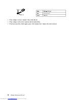
Страница 102: ... tool antenna RF connector 08K7159 USB 2 0 CD RW DVD ROM combo drive II 40Y8687 USB cable 40Y8704 USB floppy diskette drive for maintenance diskette 05K9283 USB floppy diskette drive tool kit 27L3452 Test card for integrated Smart Card 42W7820 LENOVO ThinkPad Hardware Maintenance Diskette Version 1 76 or later Note Download the file from the following Web site http www lenovo com support 96 Hardwa...

Страница 103: ...r the program s described in this publication at any time without notice The products described in this document are not intended for use in implantation or other life support applications where malfunction may result in injury or death to persons The information contained in this document does not affect or change Lenovo product specifications or warranties Nothing in this document shall operate ...

Страница 104: ...nal Business Machines Corporation in the United States other countries or both Windows is a trademark trademarks of the Microsoft group of companies The following terms are trademarks of Intel Corporation or its subsidiaries in the United States other countries or both Intel Intel Centrino Intel Core Other company product or service names may be the trademarks or service marks of others 98 Hardwar...

Отзывы: