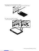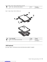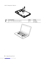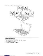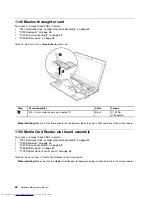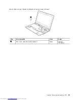
Table 13. Installation of the keyboard
When installing the keyboard, do as follows:
1. Attach the connectors.
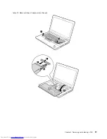
2. Attach the keyboard so that the keyboard edges are under the frame as shown in the following figure.
3. Secure the keyboard by tightening the screws from the bottom side of the computer.
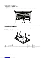
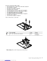
1040 Top case assembly
For access, remove “1020 Hard disk drive or solid state drive assembly” on page 54.
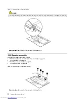
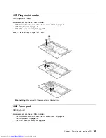
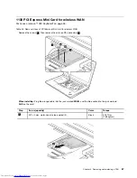
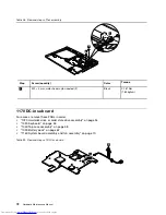
Table 14. Removal steps of top case assembly
1
1
1
1
1
1
1
1
1
Step
Screw (quantity)
Color
Torque
1
M2 × 3 mm, wafer-head, nylon-coated (8)
Black
0.181 Nm
(1.85 kgfcm)
58
Hardware Maintenance Manual
Содержание 440128U
Страница 1: ...Hardware Maintenance Manual ThinkPad Edge E420s ...
Страница 6: ...iv Hardware Maintenance Manual ...
Страница 11: ...DANGER DANGER DANGER DANGER DANGER Chapter 1 Safety information 5 ...
Страница 12: ...DANGER 6 Hardware Maintenance Manual ...
Страница 13: ...PERIGO PERIGO PERIGO Chapter 1 Safety information 7 ...
Страница 14: ...PERIGO PERIGO PERIGO PERIGO PERIGO DANGER 8 Hardware Maintenance Manual ...
Страница 15: ...DANGER DANGER DANGER DANGER DANGER Chapter 1 Safety information 9 ...
Страница 16: ...DANGER DANGER VORSICHT VORSICHT VORSICHT 10 Hardware Maintenance Manual ...
Страница 17: ...VORSICHT VORSICHT VORSICHT VORSICHT VORSICHT Chapter 1 Safety information 11 ...
Страница 18: ...12 Hardware Maintenance Manual ...
Страница 19: ...Chapter 1 Safety information 13 ...
Страница 20: ...14 Hardware Maintenance Manual ...
Страница 21: ...Chapter 1 Safety information 15 ...
Страница 22: ...16 Hardware Maintenance Manual ...
Страница 24: ...18 Hardware Maintenance Manual ...
Страница 25: ...Chapter 1 Safety information 19 ...
Страница 26: ...20 Hardware Maintenance Manual ...
Страница 27: ...Chapter 1 Safety information 21 ...
Страница 28: ...22 Hardware Maintenance Manual ...
Страница 32: ...26 Hardware Maintenance Manual ...
Страница 56: ...50 Hardware Maintenance Manual ...
Страница 63: ...Table 12 Removal steps of keyboard continued 3 3 4 8 7 5 6 Chapter 8 Removing and replacing a FRU 57 ...
Страница 81: ...Table 30 Removal steps of LCD unit continued 3 4 4 4 4 Chapter 8 Removing and replacing a FRU 75 ...
Страница 90: ...Overall 1 2 4 5 7 9 13 18 14 15 19 8 12 11 17 16 10 6 3 84 Hardware Maintenance Manual ...

