Page 41
507232-02
9/2015
Optional Power Exhaust
General
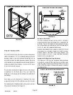
Unit may contain one or two power exhaust fans or
blowers. Exhaust blowers are shown in figure 40. Exhaust
fans are located in the same place and discharge air in the
same direction.
FIGURE 40
POWER EXHAUST BLOWERS
B35 POWER
EXHAUST
BLOWER 1
B36 POWER
EXHAUST
BLOWER 2
Units equipped with a single
power exhaust fan or blow
er are positioned in the B35
Exhaust Blower 1 location.
Power exhaust equipped with two fans or blowers is
operated in two stages. Power exhaust blowers may be
equipped with a variable frequency drive (VFD) A137 to
vary exhaust air CFM.
The Unit Controller will use damper position or building
static pressure to initiate power exhaust.
Optional Power Exhaust Variable Frequency Drive
Power Exhaust VFD (A137) will increase exhaust air CFM
when building pressure is higher than setpoint and
decrease the volume when building pressure is lower than
setpoint. The default setpoint is 0.1”w.c.
Power exhaust VFD is available with one or two blowers;
only one VFD is required. The power exhaust VFD is
located in the return air compartment on the back side of the
unit. See figure 41.
Power Exhaust Control Options
Damper Position
The Unit Controller will initiate stage 1 power exhaust when
economizer or outdoor air damper travel reaches 50%. The
Unit Controller will initiate stage 2 power exhaust when
economizer or outdoor air damper travel reaches 75%.
Refer to the Unit Controller manual ECTO 8.20 and 8.23 to
adjust the default setting.
FIGURE 41
POWER EXHAUST VARIABLE FREQUENCY DRIVE
POWER
EXHAUST
VFD (A137)
OUTDOOR
AIR
SECTION
VIEW SHOWN
FROM BACK
SIDE OF UNIT
Pressure Switches (S37 and S39)
Field-installed switches are used to sense the static
pressure difference between outdoor air and building air.
Power exhaust equipped with one fan or blower uses one
switch (S37). Power exhaust equipped with two fans uses
both switches.
Stage 1 power exhaust will be energized above 0.1”w.c.
(default) building static pressure. Stage 2 power exhaust
will be energized if building static pressure rises above
0.2”w.c. (default). Use ECTO 8.20 to adjust stage 1 setpoint
and ECTO 8.23 to adjust stage 2 setpoint.
Install the switches according to manufacturer's
instructions. Use a field-provided Outdoor Kit on the
outdoor (reference) air tubing to prevent pressure
fluctuations due to wind gusts.
Pressure Transducer (A34)
The optional factory-installed pressure transducer is used
to sense the static pressure difference between outdoor air
and building air. The transducer is located in the return air
section of unit near the supply air VFD (A96). See figure 33.
Only one pressure transducer is needed regardless of
number of exhaust blowers.
Stage 1 power exhaust constant air volume will be
energized above 0.1”w.c. (default) building static pressure.
Stage 2 power exhaust constant air volume will be
energized if building static pressure rises above 0.2”w.c.
(default). Use ECTO 8.20 to adjust stage 1 setpoint and
ECTO 8.23 to adjust stage 2 setpoint. Power exhaust
equipped with a VFD will vary the CFM output to maintain a
building static pressure of 0.1”w.c.
Complete transducer installation as follows:

