Page 42
LGH/LCH420, 480, 540, 600
1- Connect field-provided 1/4” tubing to the (+) port on the
transducer. Route tubing through unit return air opening
to a return air grille in the ductwork.
2- Locate the outdoor air kit shipped in a box in the unit
filter section. Install outdoor air kit on the top of the unit
in location shown in figure 42. Use manufacturer's
instructions.
Note - Outdoor kit reduces fluctuations in reference reading
due to wind gusts.
3- Locate the tubing provided with the outdoor air kit.
Route the tubing from the outdoor kit through the hole
under the intake hood to A34 as shown in figure 42.
Connect tubing to the (-) port on the transducer. Coil
and secure excess tubing - do not cut.
FIGURE 42
ROUTE TUBING TO OUTDOOR (REFERENCE) AIR
ROUTE REFERENCE
TUBING THROUGH
HOLE TO (A34)
INSTALL OUTDOOR
AIR KIT ON UNIT
TO A34
TRANSDUCER
Power Exhaust VFD By-Pass Plug (Optional)
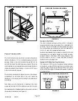
The power exhaust VFD may be by-passed using jack/plug
connections. Locate J/P211 connectors in control box area
under the relays. Disconnect J211 from P211 and connect
J215 to P211. See figure 43. Exhaust blower will operate at
maximum speed.
FIGURE 43
POWER EXHAUST VFD BY-PASS CONNECTOR
CONNECTORS USED
FOR EXHAUST VFD
OPERATION
CONNECTORS USED TO BY-
PASS VFD AND OPERATE
EXHAUST BLOWER AT
MAXIMUM SPEED
J211
P211
J215
P211
Optional Outdoor Air Dampers
Unit may contain optional outdoor air dampers which
provide fresh outdoor air. Dampers are either motorized or
manually set. Motorized dampers are controlled by the Unit
Controller. Manual dampers are adjusted and remain in the
same position. Set the damper minimum position in the
same manner as the economizer.
Optional Barometric Relief Dampers
Unit may contain optional barometric relief dampers in the
unit return air compartment to relieve excess building
pressure. Remove shipping strap and replace screws
before operation. No adjustments are necessary.
Optional Outdoor Air / Barometric Relief
Hoods
Hoods are shipped in the filter section.
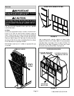
1-Remove the shipping covers over the outdoor air
openings.
2-Assemble hoods as shown in figure 44.
3-Secure hoods to unit as shown in figure 45. Outdoor air
filters are factory-installed in unit.
4-When installing outdoor air hoods, secure hinged panel
on screen to unit . See figure 46. Install two screws to
hold screen in place.
FIGURE 44
ASSEMBLE HOOD

