Page 40
LGH/LCH420, 480, 540, 600
open at approximately 73°F. If the space temperature is too
warm, change the ODE STPT to “13.6” and the Unit
Controller will allow dampers to modulate open at
approximately 70°F.
TABLE 22
FREE COOLING SETPOINT - ODE STPT MODE
Enthalpy Setpoint
°
F (
°C)*
Menu Entry - mA
Counts
73 (23)
12.0
150
70 (21)
13.6
173
67 (19)
15.5
199
63 (17)
17.6
224
*
Approximate
temperature at 50% relative humidity.
Free Cooling Differential Enthalpy - DIFF OFFSET
The Unit Controller allows damper modulation when
outdoor air is lower than return air by a differential or offset
temperature and humidity range. To set an offset range of
7°F at a constant relative humidity, enter “4” at the DIFF
OFFSET menu prompt. If return air is 76°F, the Unit
Controller will allow damper to modulate open at
approximately 69°F outdoor air. See table 23. If the space
temperature is too cool or dry, change the DIFF OFFSET to
“3” and the Unit Controller will allow dampers to modulate
open at approximately 71°F outdoor air.
TABLE 23
FREE COOLING SETPOINT - DIFF OFFSET MODE
*Temperature
Offset °F
**Relative Hu
midity Offset %
Menu Entry
mA
Counts
2
6
1
13
3.5
12
2
26
5.3
18
3
39
7
24
4
53
*
At a constant relative humidity. **At a constant temperature.
C-Damper Minimum Position Setting
Use the menu path in figure 36 to set the minimum % open
damper position when outdoor air is not suitable for free
cooling. The minimum setpoint range is 0% open (dampers
closed) to 100% (dampers fully open). On units with staged
supply air blowers, refer to the
Supply Air Variable Frequency
Drive
section in this manual
D-Units Equipped With An Energy Recovery Wheel
The economizer minimum damper position must be
adjusted to allow for the air resistance of the ERW.
1- Determine the required outdoor air CFM.
2- Apply the CFM to table 24 to determine the target static
pressure drop across the ERW.
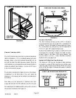
3- Measure the static pressure drop across the ERW. See
figure 39.
4- Adjust the minimum % open damper position (see
previous section).
5- Read the static pressure drop across the ERW and
adjust the minimum % open damper position as needed
to reach the target pressure drop.
TABLE 24
ERW PRESSURE DROP
Outdoor Flow - cfm
Static Pressure - in. w.c.
3250
0.45
3500
0.48
3750
0.52
4000
0.55
4250
0.59
4500
0.62
4750
0.66
5000
0.69
5250
0.73
5500
0.76
5750
0.80
6000
0.83
6250
0.87
6500
0.90
6750
0.94
7000
0.97
7250
1.01
7500
1.04
7750
1.08
8000
1.11
8250
1.15
8500
1.18
8750
1.22
9000
1.25
For example, a unit with an outdoor air flow of 6500 CFM
would require an ERW pressure drop of 0.9”w.c.
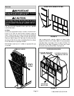
MEASURE ERW PRESSURE DROP
FIGURE 39
RETURN
AIR
POWER
EXHAUST
Measure the static pressure
drop across the ERW
OUTDOOR
AIR


