background image


1997-2001 FLH Renegade– Rev. 3  

Final Trike Inspection 


 Good 

Rework 

1.  Reflectors Installed 


2.  Lights and horn work 


3.  Park brake operation 


4.  Engine/Transmission oil levels 


5.  Belt tension 5/16”-3/8” 


6.  Wheel torque 

85 ft. lbs. (75 ft. lbs.-wire)


7.  Rear tire pressure 

26 psi


8.  Front tire pressure 

36 psi


9.  Trunk clean and dry 


10.  Trunk door seals and operates smoothly 


11.  Shocks set @ mid setting 


12.  Heat shields, side covers 


13.  Renegade/Lehman badge installed 


14.  Accessories (if applicable) 


15.  No paint defects 


16.  Warranty/owner’s manual included 


37 

Содержание Renegade

Страница 1: ...1997 2001 FLH Renegade Rev 3 1997 2001 H D TOURING MODELS INSTALLATION INSTRUCTIONS 1997 01 MODELS REQUIRE BELT UPGRADE December 2013 ...

Страница 2: ...talling Exhaust Lights and Wiring Body Neck Race Preload Motor Mounts General Information Replacement Parts Renegade Torque Specifications Final Trike Inspection Notes before starting conversion For 1997 01 models the standard Lehman Renegade conversion will not accommodate the original 1 1 2 final drive belt The following belt replacement is required to properly complete the Renegade installation...

Страница 3: ...or this information refer to the factory service manual The information in these instructions is provided to Lehman Trike dealers It is proprietary to Lehman Trikes Inc and provided solely for use by dealers Any unauthorized duplication or distribution is a vio lation of international copyright law 3 This is the safety alert symbol When you see this symbol on your machine or in this manual be aler...

Страница 4: ...ct your eyes by using proper safety glasses or goggles Read through the installation instructions before you begin Make sure you have all the proper tools parts and skill set to perform the installation safely and completely NOTE Compliance with national DOT USA MOT Canada State Provincial and local vehicle is standards is the responsibility of the installer Installation of the parking brake and g...

Страница 5: ...cking the Kit The crate contains the following Body Differential with brakes Tires mounted on rims Boxed swingarm Lehman frame Hardware box containing smaller parts and bolt bags Warranty Book Owner s Manual Packing parts list 5 Fig 1 ...

Страница 6: ...1997 2001 FLH Renegade Rev 3 6 LS2009 1997 2001 SWINGARM LF2084 FRAME MODULAR DIFFERENTIAL ...

Страница 7: ...e side stand mounting bolt and separate side stand from bracket 8 Remove passenger footboards Save boards and hardware for re installation 9 Remove side covers 10 Remove rear side cover grommets from motorcycle for use with Lehman side cover mounts 11 Remove saddlebags if equipped 12 Remove mufflers and saddlebag mounts Keep all muffler mounting hardware including rubber iso lators located in sadd...

Страница 8: ...an swingarm following H D service manual procedure Bearings should bottom out on stop in Lehman swingarm collar Note Refer to H D service manual for swingarm installation procedures and torque specifica tions for specific model of motorcycle 3 Install Lehman swingarm with word TOP stamped into swingarm collar facing upward Use Loc tite 242 on threads Torque rear swingarm fork pivot shaft to 45 ft ...

Страница 9: ...e length as OEM motor mount link 4 See Fig s 2 3 Position top reinforcement plates LB1040 and side plates LP1200 against frame and out line around them 5 See Fig s 2 3 Sand or grind frame to bare metal finish inside outline where brackets will fit A slightly rough sur face is desirable Note Use a generous amount of glue Loctite 330 to fill between bracket and frame Apply glue to plate and spray ac...

Страница 10: ...ts LB1040 frame shim washers and lock nut Use 2 3 C clamps to hold bracket to frame Use 1 C clamp to hold side reinforce ment plates LP1200 to frame 7 Allow adhesive to cure for 24 hours 8 Installation may proceed while glue cures 9 Attach link assembly to upper frame mounting bracket Fig 4 10 ...

Страница 11: ...5 11 Tighten all bolts to factory torque specs frame 22 ft lbs engine 33 ft lbs 12 Check for any interference of motorcycle parts wire harnesses air hoses etc 13 Reroute any wire harnesses around or behind bracket The coil wire on a fuel injected model will run over top edge of bracket Note Make sure harnesses are not pinched when fuel tank is reinstalled Fig 5 ...

Страница 12: ...cured FLH Lower Engine Mount Bolt 1 Remove 3 8 bolt lock washer and flat washer that holds engine stabilizer to engine 2 Apply blue Loctite 242 to threads of 3 8 x 1 1 2 hex flange locking bolt 3 Install 3 8 x 1 1 2 flanged bolt and original washer Torque bolt to 42 ft lbs 4 On same bolt install 3 8 supplied locknut and torque to 38 ft lbs 5 Remove bolt lock washer and flat washers that hold stabi...

Страница 13: ...ingarm as shown Leave hardware loose 2 See Fig 2 Attach RH adapter plate to swin garm as shown with park brake bracket mounted to lower holes Leave hardware loose 3 See Fig 1 and 2 Install 3 8 nut to adjuster bolt and thread into adapter plate from backside Run bolt completely into adapter plate Fig 1 Fig 2 ...

Страница 14: ...1997 2001 FLH Renegade Rev 3 14 4 See Fig 3 and 4 Loosely install hardware to pinch blocks before installing differential to swingarm Fig 3 Fig 4 ...

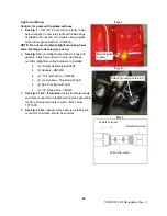
Страница 15: ...fferential as far forward as possible Set jack stands under axle tubes 8 Tighten pinch block hardware just enough to allow differential to slide on swingarm adapter plates 9 See Fig 5 Remove upper lower and rear housing plates 10 See Fig 6 Carefully slide belt over pulley Reinstall housing plates with original hardware us ing Loctite 242 Install all hardware before tighten ing Torque hardware to 1...

Страница 16: ...torque to 35 ft lbs 6 Once tracking is obtained re check belt tension Raise and lower differential assembly slowly with a jack while checking belt tension When tightest position is located apply 10 lbs force at midpoint of lower strand of belt Correct deflection is 5 16 3 8 7 Increase or reduce belt deflection by turning adjuster screw on each side in or out an equal number of turns 8 Look along t...

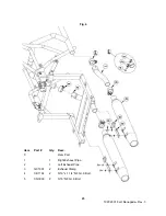
Страница 17: ...ing the following hardware 1 Brass Tee CF5105 1 Spacer S001530 2 1 4 x 1 3 4 Hex Bolt CB1100 2 1 4 Flat Washers CW2005 2 1 4 Lock Nut CN3042 2 See Fig 1 Install original brake line from master cyclinder and rear braided lines to brass tee using the following hardware Torque banjo bolt to 16 ft lbs 1 Banjo Bolt S002022 2 Banjo Washers GC6002 2 45 M10 Braided Line S001976 3 See Fig 2 Install 2 braid...

Страница 18: ...rements to brake system and work brakes to fill lines 7 Remove rubber caps on bleeder valves Install clear brake bleeder hose over bleeder valve on caliper 8 Pump brake pedal to build pressure 9 While holding the brake pedal open bleeder valve to release pressure and remove air from system Repeat bleeding on both calipers until fluid is solid without bubbles in bleeder hose 10 Tighten bleeder valv...

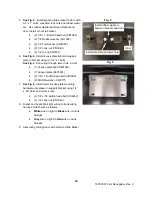
Страница 19: ...frame attach ing cable ties to cable and frame and install in left hole in handle mount 6 See Fig 7 Route right park brake cable up around axle and forward to right hole in handle mount 7 See Fig 7 Secure both cables to upper rear pinch block with clamp GC0108 8 See Fig 8 Secure cable retaining nuts to handle mount with 7 8 wrench 9 Check for tire clearance 10 See Fig 8 Thread one 5 16 NF nut onto...

Страница 20: ...plates LB1220 to Leh man frame plate using 5 16 X 1 bolts flat washers and a lock nuts 4 See Fig 2 Level Lehman frame to H D frame Frames should be parallel with each other Tighten all bolts when level Torque front 1 2 bolts to 78 ft lbs Torque all frame plate bolts to 19 ft lbs 5 See Fig 3 Lower differential and install 1 2 X 2 1 4 bottom shock bolt through lower shock eye and thread it into shoc...

Страница 21: ...n right side of trike behind top bolt on electronic control module Re route air lines to fit 12 Charge system with air 20 psi and check for leaks with soapy water 13 A plastic imitation fender is used to mount seat and grab handle Imitation fender will use original motorcycle fender mounting hardware Front of imitation fender mounts in same location as origi nal fender Rear of imitation fender mou...

Страница 22: ...e This pipe may need to be tilted downward to achieve proper angle with muffler 4 See Fig 2 Cut 1 3 4 off back of Lehman supplied LH drop pipe LP1350 5 See Fig 2 Cut 5 1 2 off back of Lehman supplied RH drop pipe LP1351 6 Trim heat shields as needed for proper fitment 7 Fasten exhaust clamps to joint using 5 16 X 1 1 4 NF Gr 8 bolt and 5 16 NF Gr 8 nut Position clamp so they do not squeeze a slit ...

Страница 23: ...997 2001 FLH Renegade Rev 3 23 Fig 4 Item Part Qty Desc 0 Oem Part 1 1 Right Exhaust Pipe 2 1 Left Exhaust Pipe 3 GC1001 2 Exhaust Clamp 4 CB1164 2 5 16 x 1 1 4 NF Gr 8 Bolt 5 CN3009 2 5 16 NF Gr 8 Bolt ...

Страница 24: ... Attach ground wire to stud with flange nut after taillight mounting hardware is installed 2 Taillight Assembly S002204 2 Gaskets BG0200 4 1 4 Flat Washer CW2006 4 Lock washer Provided with light 4 Nut Provided with light 2 1 4 Flange Nut CN3007 3 See Fig s 3 4 If required Install female terminals and male connectors to taillight wiring Use appropriate tool for crimping terminals to wires Mac Tool...

Страница 25: ...h lower hole in door 1 License plate light S001469 1 Support plate S001601 2 1 4 x 1 Button head bolt CB1086 2 M6 Flat washer CW2175 7 See Fig 6 Install lower license plate mounting hardware into place on support bracket using 1 4 x 50 bolts and 2 lock nuts 2 1 4 x 50 Button head bolt CS4032 2 1 4 Lock nut CN3040 8 Solder and heat shrink light wiring to trunk wiring harness Attach wire as follows ...

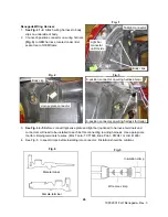
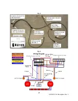
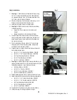
Страница 26: ...s will need to be installed to each before connecting to wiring harness Use appropriate tool for crimping terminals to wires Mac Tools TCT1028 Blue Point PWC47 or H D 41609 4 See Fig 5 Inspect crimps before installing into connector Distortion should be minimal 26 Fig 3 8 position connector on wiring harness main 6 position connector on wiring harness for trailer Fig 1 Body clips Light bar connect...

Страница 27: ...nector under seat GH0023 1 License plate connector GH0023 3 Right brake light GH0023 3 Light bar GH0023 5 Left brake light GH0023 4 Left turn signal GH0023 4 Right turn signal GH0023 4 Included in bag Wiring Diagram Purple Blue Orange White Tracer Brown Black Red White Tracer Black Orange White Tracer ...

Страница 28: ... hole centered in slot of each of tabs 6 Fasten body to Lehman frame as follows Head of bolt will be inside trunk 4 1 4 x 1 1 2 Button Head Bolts CS4031 4 1 4 x 1 1 4 Fender Washers CW2108 4 Foam Sealing Washers FG1002 4 1 4 Flat Washers CW2007 4 1 4 Lock Nuts CN3041 7 See Fig 5 Install upper body braces LB1235 by at taching slotted side on top of Lehman frame using the following hardware Leave ha...

Страница 29: ...cket FB1036 2 Aluminum Crimp CC1900 3 Apply masking tape to body just below hinge mounting holes to prevent scratching of paint by hinges 4 See Fig 3 Install door hinges and stop cable brackets to body with hinge gaskets underneath hinge using 10 32 x 1 screws and plated star nuts 2 Door Hinge GH0903 2 Hinge Gaskets FG1003 4 10 32 x 1 Phillips Screws CS4024 0 4 Plated Star Lock Nuts CN1898 5 Faste...

Страница 30: ...and 1 4 bolts 2 1 4 x 1 2 Bolts CB1075 2 1 4 Lock Washers CW2040 14 Install Renegade badge to bottom right side of door Install Lehman badge GB1320 to bottom left side of door 1 Renegade Badge GB1324 1 Lehman Badge GB1320 15 Cut license plate wire from body to length to reach body wiring as needed 16 Install shrink tubing over license plate wires 17 Strip and solder ends of license plate wires fro...

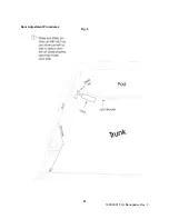
Страница 31: ...1997 2001 FLH Renegade Rev 3 Door Adjustment Procedures 31 Fig 6 ...

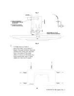
Страница 32: ...1997 2001 FLH Renegade Rev 3 32 Fig 7 Fig 8 ...

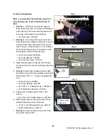
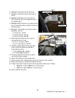
Страница 33: ...to body 3 Set tour pack into place where it is comfortable check front to back and side to side Seat may be set in place to help locate tour pack Carefully open tour pack and locate 8 holes in metal plate in floor Drill forward 4 mounting holes in tour pack plate and body to 21 64 4 Attach tour pack using 4 5 16 X 2 bolts lock washers flat washers and tour pack supports LS1028 inside trunk Now tha...

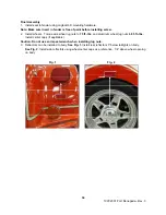
Страница 34: ...s Torque wire wheel lug nuts to 75 ft lbs and aluminum wheel lug nuts to 85 ft lbs Install center caps if applicable Caution Do not use an impact wrench when installing lug nuts 3 Reflectors can be installed to body See Fig 1 Install rear reflectors 3 below taillights on body See Fig 2 Install side reflectors using wheel center caps as a reference 1 4 above wheel opening on body 34 Fig 1 Fig 2 ...

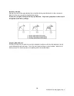
Страница 35: ...t tighten bolts past factory specifications Only bearing adjustment collar should be tightened past factory settings Adjusting Motor Mounts The front and top motor mounts may need to be adjusted to achieve correct vertical alignment and to center differential housing to frame To do this trike must be sitting on a level surface Refer to H D service manual for correct procedure on adjusting motor mo...

Страница 36: ...dapter plate to swingarm 35 ft lbs Banjo bolts 16 ft lbs Torque link to frame 22 ft lbs Torque link to engine 33 ft lbs Lehman frame to H D frame 78 ft lbs Frame plate bolts 19 ft lbs Frame brace 35 ft lbs Shock bolts 40 ft lbs Wheels aluminum 85 ft lbs Wheels wire 75 ft lbs Caliper to bracket bolts 38 ft lbs Caliper bracket to axle flange bolts 38ft lbs Differential housing plate bolts 17ft lbs A...

Страница 37: ...ls 5 Belt tension 5 16 3 8 6 Wheel torque 85 ft lbs 75 ft lbs wire 7 Rear tire pressure 26 psi 8 Front tire pressure 36 psi 9 Trunk clean and dry 10 Trunk door seals and operates smoothly 11 Shocks set mid setting 12 Heat shields side covers 13 Renegade Lehman badge installed 14 Accessories if applicable 15 No paint defects 16 Warranty owner s manual included 37 ...

Отзывы: