LAUNCH
X-431 PAD V
User's Manual
77
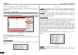
mixture gas, which has a lower ionization level and vice versa.
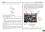
Fig. 7-42
7.4.3 Secondary-direct ignition analysis
1. Power the Scopebox on: Power is provided to the Scopebox in
either of the following ways:
• Power adapter
: Insert one end of the power adapter into the
Power interface of the Scopebox, and the other end to the AC
outlet.
• Battery clamps cable
: Plug one end of the power adapter into
the Power interface of the Scopebox, and then clamp the other
two terminals to the vehicle's battery (Red to +, and Black to -)
respectively.
2. Connect the B-shaped terminal of the data cable to the Scopebox
Data I/O port, and the other end to the Data I/O port of the
diagnostic tool.
3.
When the high-voltage wire is exposed
, plug the BNC end of
secondary ignition pickup into CH1/CH2/CH3/CH4 channel of
Scopebox, then connect the high-voltage clip to high-voltage line,
and crocodile clips to ground.
4.
If no high-voltage wire is exposed
, dismantle ignition coil of tested
cylinder. Connect one end of the COP extension cord to the ignition
coil which should be grounded via COP earth cord, and insert the
other end into the cylinder to joint with spark plug. Then plug the
BNC end of secondary ignition pickup into CH1/CH2/CH3/CH4
channel of Scopebox, and then connect the high-voltage clip to
high-voltage line, and crocodile clips to ground.
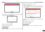
The connection is as follows:
COP earth
cord &
crocodile clips
to ground
Ignition coil
COP earth cord
COP extension
cord
The high-voltage clips to
the insulated lead of the
COP extension cord
Spark plug
Fig. 7-43
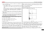
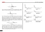
Fig. 7-44 shows the normal secondary (the upper one) and (the lower
one) primary ignition waveform of direct ignition system. Beause the


