LAUNCH
X-431 PAD V
User's Manual
53
among the ports of sensor in order to determine whether open-
circuit / contact fault exists or not.
•
When checking if there is a short in the line, please disconnect the
CEU and the relevant sensor, then measure the resistance value of
the ports between the connected port and the vehicle body. If the
resistance value is more than 1MΩ, no fault occurs.
•
Before disassembling the engine electrical control system cable,
cut off the power supply, that is, turn the ignition switch OFF and
disconnect the cables on the battery poles.
•
Contact the test probe and the two terminals/ the two leads to be
measured when measuring the voltage between the two terminals
or the two leads.
•
Contact the red test probe to the terminal/ the cable to be
measured, and the black probe to the ground when measuring
voltage of one terminal/ one cable.
•
When checking the continuity of the terminals, contacts and leads,
the method for measuring their resistances can be used.
•
Check the faults in the terminals of the CEU to sensors, relays, etc.
•
There are two test probes in the testing wire. The black one is the
common signal terminal (signal GND); the red one is the input
terminal for voltage, resistance, and frequency test and output
terminal for simulation voltage, simulation frequency and oxygen
sensor. Please choose the correct probes to match the different
terminals.
7.1.4 Multimeter
7.1.4.1 Operations
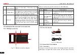
Make sure the diagnostic tool and the Sensorbox are properly
connected, power on the diagnostic tool and enter the Applications
menu interface, tap “Multimeter” to display the test menu.
Fig. 7-9
Click the desired test as shown above to perform related test.
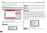
The operation method on
Resistance test
and
Frequency test
is
identical to that of Voltage test. Here just take Voltage test as an
example for demonstration.
Fig. 7-10
The following operations can be done:
[ ]: Erases the currently displayed waveform and display it starting

