


64
LAUNCH
X-431 PAD V
User's Manual
11
Back Probe Pins
Suite
T
hey are mainly used for piercing the
insulation of wires to allow for automotive
electrical measurements without causing
damage to the wires. Additionally they can
be used as pin-tip probes while working
with small circuit boards.
7.3.3 Connection & Initial Use
7.3.3.1 Probe Compensation
Perform this function to match the characterist
i
cs of the probe(optional)
and the channel input. The probe that has not been compensated may
cause measurement tolerance or error.
1. Set the switch to "X10" (the default is X1) on the probe and connect
it to the any Channel of the Scopebox.
2. Follow Steps 1-2 in Item 2 "Connection" mentioned below to
connect the Scopebox and diagnostic tool. Launch the App and
open "Scope" to run it.
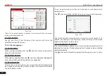
3. From the "Vertical Setting" menu, select the corresponding channel
and set the Probe attenuation to 1:10.
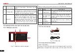
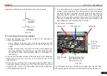
4. Attach the probe tip to the Probe Compensator and the ground
nip of the reference lead to the ground connector. When using the
probe hook-tip, insert the tip onto the probe compensator firmly to
ensure a proper connection.
Probe Compensator
Ground Connector
Fig. 7-21
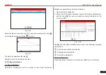
5. Tap the
button located on the bottom of the screen, a square
wave (approximately 1kHzm 2V peak-to-peak) will be displayed
within several seconds.
*Note: The above steps also can be applied to check whether the signal
input/output of other Channels are normal or not.
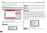
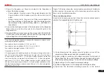
Check the shape of the displayed waveform to determine whether
the probe is correctly compensated.
Correctly
Compensated
Over
Compensated
*Note: If necessar y,
use a non-metallic tool
to adjust the trimmer
capacitor of the probe for
the fattest square wave
being displayed on the
Scopebox.
Under
Compensated