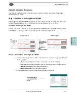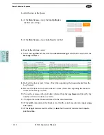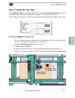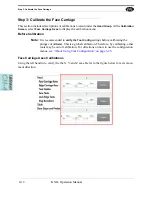
Step 5: Calibrate Lock Edge Tools (Option)
KVAL Operation Manual
4-16
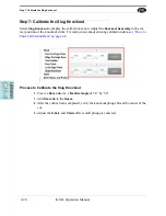
Step 5: Calibrate Lock Edge Tools (Option)
This section focuses on the
Edge Tool Calibration
. For instructions about entering calibration data,
see “How to Enter Calibration Data” on page 4-6.
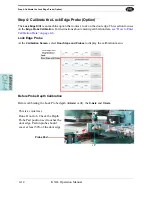
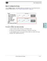
About the Edge Carriage Axis
Do
not
adjust a cut with the
Edge Carriage Axis Calibration
. The calibration is to be used by
trained Service Technicians.
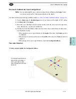
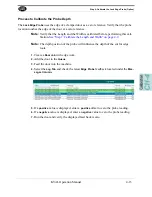
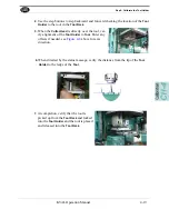
Process to Calibrate the Lock Edge Tool
1.
Create a
Door Job
of a
Lock Cut
of your choice
2.
Add
Door Job
to the
Queue
.
3.
Once the cut is machined, measure the
length
,
width
, and
depth
positions of the cut.
If the cut is not in the specification, determine which axes need to be calibrated.
4.
Perform the
Left Hand Rule
pointed at the cut lock to determine axis direction. See
illustration below.
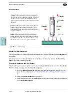
• If the
length
position of the lock cut is out of specification, the
X-Axis
needs to be
adjusted.
• If the
width
position of the lock cut is out of specification, the
Y-Axis
needs to be
adjusted.
• If the
depth
cut is out of specification, the
Z-Axis
needs to be adjusted.
To determine axis direction.
Stand at the Lock Side of Door, point at the lock edge of the door with the left hand rule.
+
X
+
Z
-
X
-
Y
-
Z
+
Y
Содержание DL-NCD
Страница 10: ...KVAL DL NCD Operation Manual Table of Contents ...
Страница 28: ...How to Download the Service Application KVAL Operation Manual 1 18 ...
Страница 30: ...Safety Sign Off Sheet KVAL Operation Manual 1 20 ...
Страница 62: ...About the LiteCutout Feature Detail KVAL Operation Manual 2 32 ...
Страница 94: ...Appendix About Backing up the Data KVAL Operation Manual 3 32 ...
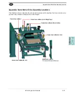
Страница 118: ...Appendix Servo Motor Drive Assembly Locations KVAL Operation Manual 4 24 ...
Страница 139: ...About the Electrical Panels KVAL Operation Manual 5 21 I ...
Страница 142: ......
Страница 143: ......


