ADJUSTMENT
60
C
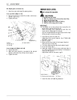
Aligning the control levers
1. Stop the engine and apply the parking brake.
Lever position (High or Low)
2. Remove the bolts and select the motion control lever
position, high or low.
3. Tighten the bolts.
Lever alignment (Right and Left)
4. Loosen the bolts.
5. Slide both levers forward or rearward to the desired
position within tab slots until levers are aligned.
6. Tighten the bolts.
MOWER DECK LEVEL
B
ANTI-SCALP ROLLERS
To avoid personal injury:
A
Park the machine on a firm and level surface.
A
Apply the parking brake.
A
Stop the engine and remove the key.
A
Wait for all moving parts to stop.
A
The flattest cut can be achieved by having the anti-
scalp rollers adjusted off the ground.
Check anti-scalp roller adjustments each time the
mower deck cutting height is changed.
It is recommended that all the anti-scalp rollers be kept
off the ground to minimize scuffing.
1. Check the machine tire pressure.
Inflate tires to the correct pressure. (See "TIRES AND
WHEELS" section.)
2. Start the engine.
3. Raise up the mower deck to the transport position.
(Also the top end of the lift.)
4. Turn the cutting height control dial to adjust height.
5. Lower the mower deck.
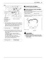
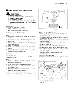
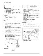
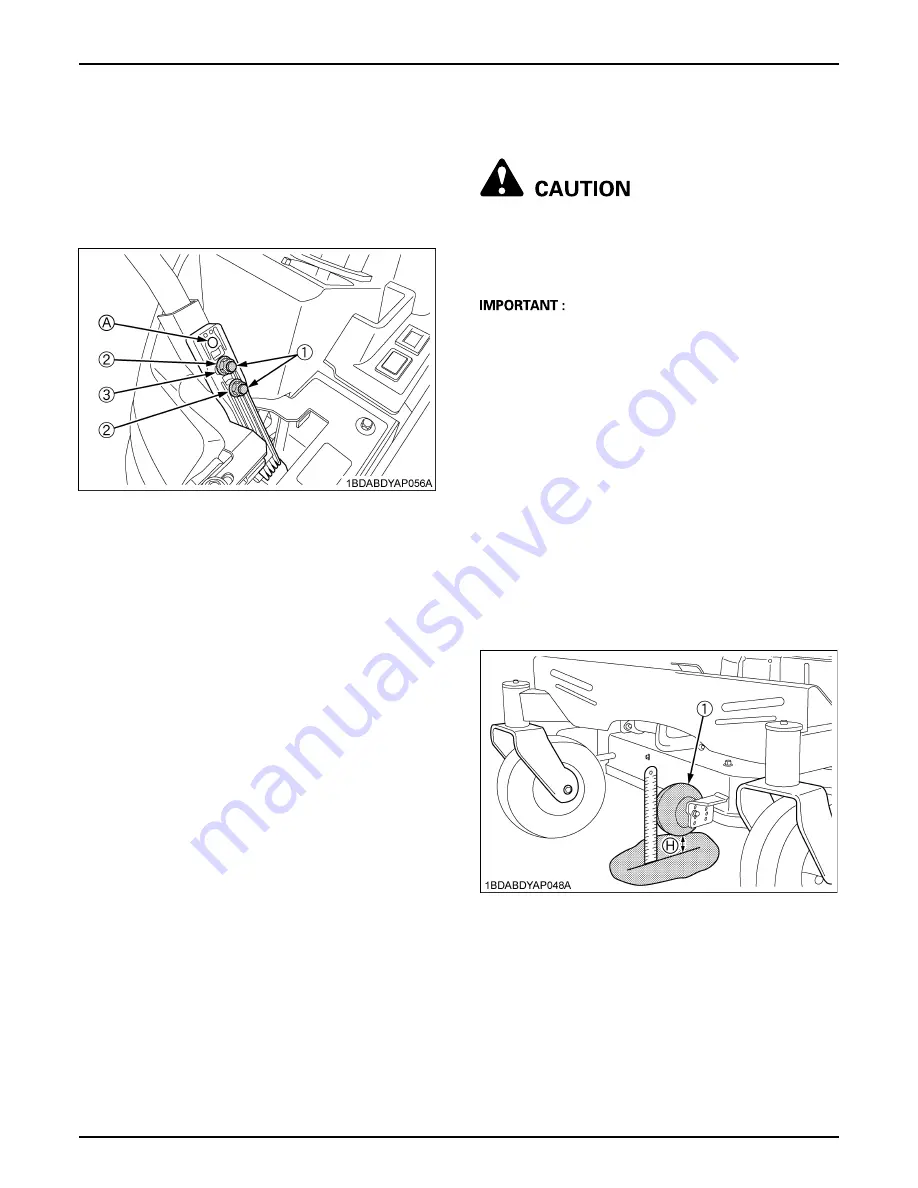
6. Adjust the height of the front side anti-scalp roller to
one of four positions to approximately 19 mm between
rollers and the ground.
Adjust three rollers to the same height.
7. Install the roller with attaching hardware.
(1) Bolt
(2) Flange nut
(3) Tab slot
(A) High position
(1) Front side anti-scalp roller
(H) 19 mm
Содержание ZG123S-AU
Страница 7: ......
Страница 12: ... 5 SAFE OPERATION 5 DANGER WARNING AND CAUTION LABELS ...
Страница 13: ...SAFE OPERATION 6 ...
Страница 14: ... 7 SAFE OPERATION ...
Страница 17: ...SERVICING OF MACHINE 2 1 Mower identification plate 2 Mower serial No 1 ROPS serial No ...
Страница 22: ...7 INSTRUMENT PANEL AND CONTROLS ILLUSTRATED CONTENTS 1 Anti scalp roller Front bolt shift type 22 ...

