53
PERIODIC SERVICE
C
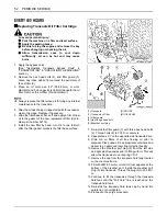
Purging Procedures
Due to the effects air has on efficiency in hydrostatic drive
applications, it is critical that it is purged from the system.
Air creates inefficiency because its compression and
expansion rate is higher than that of the oil approved for
use in hydrostatic drive systems.
These purge procedures should be implemented any time
a hydrostatic system has been opened to facilitate
maintenance or the oil has been changed.
The resulting symptoms in hydrostatic systems may be:
1. Noisy operation.
2. Lack of power or drive after short term operation.
3. High operation temperature and excessive expansion
of oil.
Before starting, make sure the transaxle is at the proper
oil level. If it is not, fill to the specifications outlined in this
manual.
The following procedures are best performed with the
machine drive wheels off the ground. Then repeated
under normal operating conditions. If this is not possible,
then the procedure should be performed in an open area
free of any objects or bystanders.
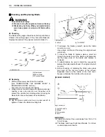
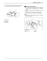
1. Disengage the brake if activated.
2. With the bypass valve open and the engine running,
slowly move the motion control levers in both forward
and reverse directions (5 or 6 times).
3. With the bypass valve closed and the engine running,
slowly move the motion control levers in both forward
and reverse directions (5 to 6 times). Check the oil
level, and add oil as required after stopping the
engine.
4. It may be necessary to repeat Steps 2 and 3 until all
the air is completely purged from the system. When
the transaxle operates at normal noise levels and
moves smoothly forward and reverse at normal
speeds, then the transaxle is considered purged.
B
Changing Transaxle Fluid
(See "Replacing Transaxle Oil Filter Cartridge" in "EVERY
400 HOURS" in "PERIODIC SERVICE" section.)
EVERY 500 HOURS
B
Electric Clutch Adjustment
The electric clutch serves two functions in the operation of
the mower. In addition to starting and stopping the power
flow to the cutter blades, the clutch also acts as a brake to
assist in stopping blade rotation when the PTO is switched
off or the operator presence control is interrupted.
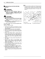
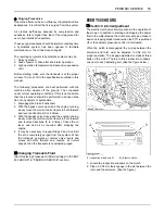
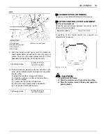
When the clutch is disengaged, the air gap between the
armature and rotor must be adjusted to 0.04 mm for
proper operation. The air gap adjustment is made at three
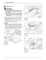
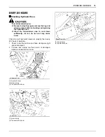
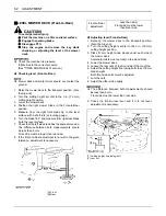
bolts on the clutch. There are three inspection windows,
one next to each adjusting bolt. (See the figure below.)
1. Locate the inspection windows on the clutch.
2. Place a 0.04 mm feeler gauge in the slot between the
rotor and the armature. (See the figure.)
(1) Inspection window (x3)
(A) Electric clutch
Содержание ZG123S-AU
Страница 7: ......
Страница 12: ... 5 SAFE OPERATION 5 DANGER WARNING AND CAUTION LABELS ...
Страница 13: ...SAFE OPERATION 6 ...
Страница 14: ... 7 SAFE OPERATION ...
Страница 17: ...SERVICING OF MACHINE 2 1 Mower identification plate 2 Mower serial No 1 ROPS serial No ...
Страница 22: ...7 INSTRUMENT PANEL AND CONTROLS ILLUSTRATED CONTENTS 1 Anti scalp roller Front bolt shift type 22 ...

