58
ADJUSTMENT
ADJUSTMENT
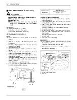
MOTION CONTROL LEVER
To avoid serious injury:
A
Park the machine on a firm and level surface.
A
If it is necessary to run the engine in an
enclosed area, use a gas tight exhaust pipe
extension to remove the fumes.
A
Always try to work in a well-ventilated area.
A
Lift up and secure with jack stands or blocking
the rear of the machine, do not run the machine
while adjusting.
Remove rear wheels.
A
Do not adjust only one of the following
adjustments; exclude "MOTION CONTROL
LEVER ALIGNMENT".
They are interlinked.
A
If you feel you are unable to make the following
adjustments correctly and safely, please
contact your local KUBOTA Dealer.
A
Right and left motion control levers can be adjusted
independently.
B
HST NEUTRAL
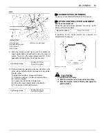
1. Lift-up and secure with jack stands or blocking the rear
of the machine frame.
2. Remove both rear wheels.
3. Start the engine, and run at maximum speed.
4. Place the motion control lever in "NEUTRAL LOCK"
position.
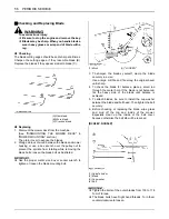
5. Loosen the three bolts of the guide plate.
Adjust the guide plate position until the rear axle
rotation stops.
6. Tighten the rear bolt and place the lever in "NEUTRAL
LOCK" position. Check that the rear axle does not
rotate.
If the axle does not stop rotating, adjust the "HST
NEUTRAL" again.
7. Adjust the other side "HST NEUTRAL" equally.
8. After adjustment, make sure to stop the engine
immediately.
[RH]
Tightening torque
23.6 to 27.4 N-m
(2.4 to 2.8 kgf-m)
(1) Guide plate
(2) Speed adjust plate
(3) Bolt (front)
(4) Bolt (rear)
(A) Motion control lever
Содержание ZG123S-AU
Страница 7: ......
Страница 12: ... 5 SAFE OPERATION 5 DANGER WARNING AND CAUTION LABELS ...
Страница 13: ...SAFE OPERATION 6 ...
Страница 14: ... 7 SAFE OPERATION ...
Страница 17: ...SERVICING OF MACHINE 2 1 Mower identification plate 2 Mower serial No 1 ROPS serial No ...
Страница 22: ...7 INSTRUMENT PANEL AND CONTROLS ILLUSTRATED CONTENTS 1 Anti scalp roller Front bolt shift type 22 ...

