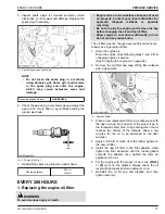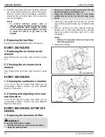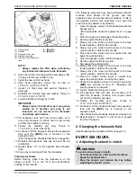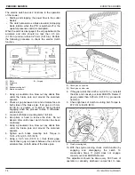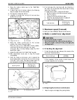
4. Place the motion control lever in the
“NEUTRAL
LOCK”
position.
5. If either rear axle is turning, observe the following
steps to adjust the neutral position.
6. Put weight on the seat cushion.
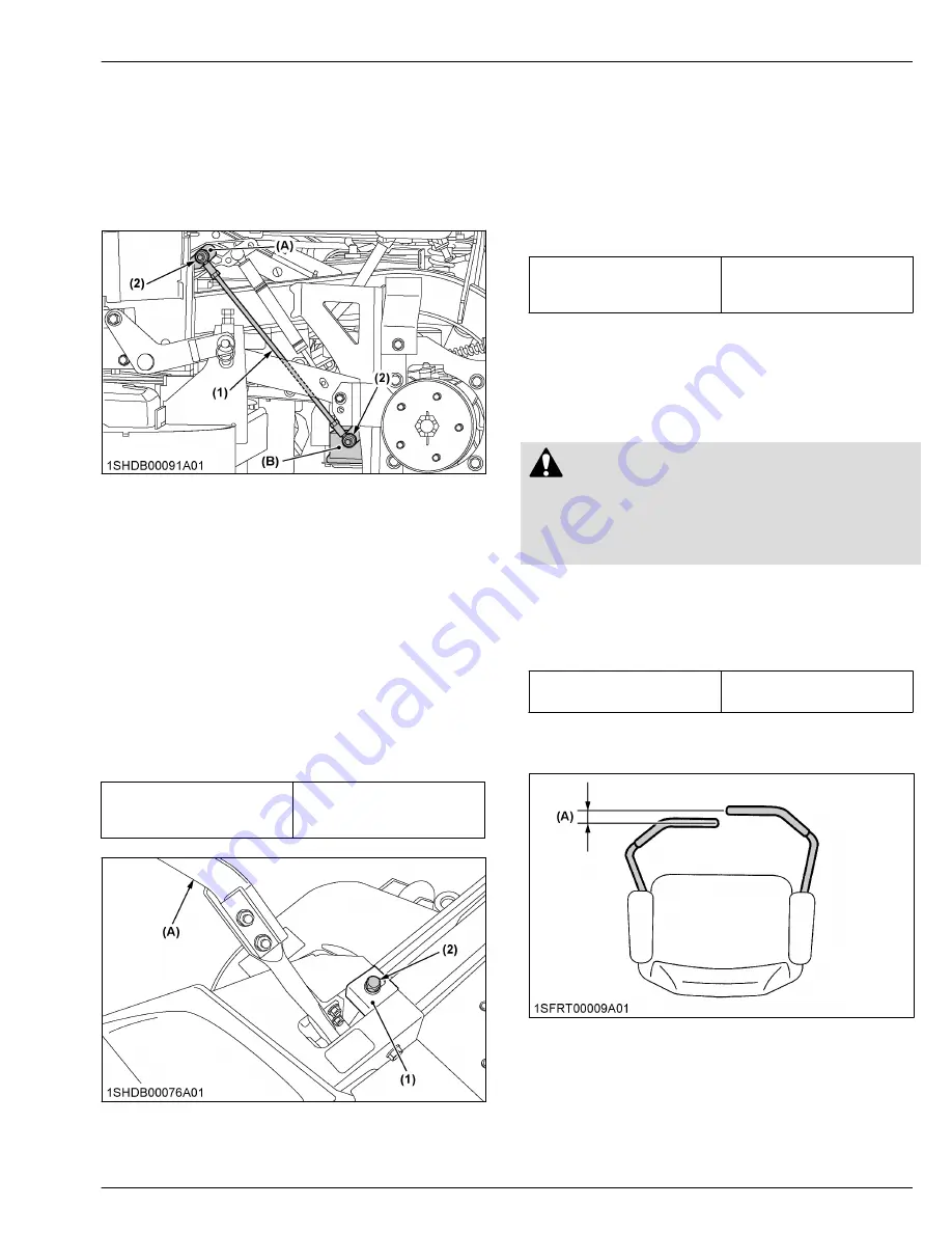
7. Lengthen or shorten the rod by 1/2 turn and then
tighten the lock nuts.
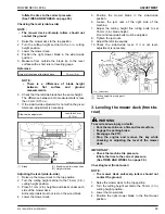
(1) Rod
(2) Flange bolt and nut
(A) Lever
(B) Transaxle
8. Place the motion control lever to the reverse
position, then move it forward slowly.
Place the lever in the
“NEUTRAL LOCK”
position,
and check that the rear axle does not rotate.
If the axle does not stop rotating, adjust the
“HST
NEUTRAL”
again.
9. Adjust the other side
“HST NEUTRAL”
equally.
10. After adjustment, make sure to stop the engine
immediately.
11. Push the motion control lever until it contacts the
speed adjust plate and reaches the end of its range
of motion. Then move the speed adjust plate 2-3
mm backward and tighten 2 front bolts securely.
Tightening torque
23.6 to 27.4 N
⋅
m
2.4 to 2.8 kgf
⋅
m
17.4 to 20.2 lbf
⋅
ft
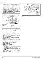
(1) Speed adjust plate
(2) Bolt
(A) Motion control lever
12. If at full speed the machine pulls one direction or
the other, it is an indication that one wheel is turning
faster than the other.
To adjust the condition, proceed as follows:
a. Park the machine on a firm and level surface.
b. Stop the engine.
c. Loosen the front bolt of faster side.
d. Move the speed adjust plate to backward.
e. Tighten the front bolt securely.
Tightening torque
23.6 to 27.4 N
⋅
m
2.4 to 2.8 kgf
⋅
m
17.4 to 20.2 lbf
⋅
ft
3. Maximum speed (forward)
Consult your local KUBOTA Dealer for this service.
4. Motion control lever alignment
WARNING
To avoid serious injury or death:
• Park the machine on a firm and level surface.
• Stop the engine, remove the key and apply the
parking brake.
4.1 Checking the alignment
1. Check the gap and space between the levers at the
maximum forward position.
Recommended gap:
0 to 2 mm
0 to 0.08 in.
If the positions of the motion control levers are
unequal, adjustment is necessary.
(A) “GAP”
4.2 Aligning the motion control levers
1. Stop the engine and apply the parking brake.
MOTION CONTROL LEVER
ADJUSTMENT
Z751KWi,Z781KWi,Z781KWTi
81
Содержание Z751KWi
Страница 3: ...OPERATOR S MANUAL 1SJGJ00001A01 READ AND SAVE THIS MANUAL MODELS Z751KWi Z781KWi Z781KWTi ...
Страница 15: ...SAFETY LABELS SAFE OPERATION 10 Z751KWi Z781KWi Z781KWTi ...
Страница 16: ...SAFE OPERATION Z751KWi Z781KWi Z781KWTi 11 ...
Страница 17: ...SAFE OPERATION 12 Z751KWi Z781KWi Z781KWTi ...
Страница 18: ...SAFE OPERATION Z751KWi Z781KWi Z781KWTi 13 ...
Страница 19: ...SAFE OPERATION 14 Z751KWi Z781KWi Z781KWTi ...
Страница 21: ...16 Z751KWi Z781KWi Z781KWTi ...
Страница 59: ...PERIODIC SERVICE CHART LABEL MAINTENANCE PERIODIC SERVICE CHART LABEL 54 Z751KWi Z781KWi Z781KWTi ...

