ROTEX
®
Operating/Assembly instructions
KTR-N
Sheet:
Edition:
40210 EN
20 of 22
22
Please observe protection
note ISO 16016.
Drawn:
2017-09-06 Pz/Bru
Replacing:
KTR-N dated 2017-01-02
Verified:
2017-09-06 Pz
Replaced by:
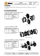
ROTEX
®
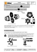
coupling
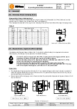
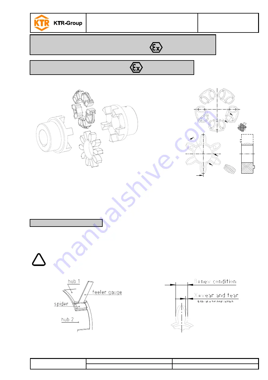
Illustration 17.1:
ROTEX
®
DZ
elements
Illustration 17.2:
ROTEX
®
spider
Illustration 16: ROTEX
®
coupling
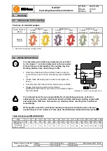
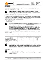
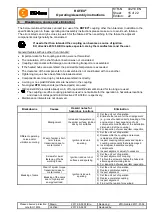
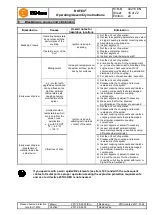
Here the backlash between the cams of the coupling and the flexible spider/DZ element must be inspected by
means of a feeler gauge.
When reaching the wear limit
maximum friction
, the spider/DZ element must be replaced immediately,
irrespective of the inspection intervals.
In case of backlash > X mm, the flexible spider/DZ elements must be replaced.
Reaching the limits for replacing depends on the operating conditions and the existing operating parameters.
!
In order to ensure a long service life of the coupling and avoid dangers with the use in
hazardous locations, the shaft ends must be accurately aligned.
Please absolutely observe the displacement figures indicated (see table 9 to 11). If the
figures are exceeded, the coupling will be damaged.
Illustration 18: Inspection of the limit of wear
Illustration 19: Wear of spider
10
Enclosure A
Advice and instructions regarding the use in
hazardous locations
10.2 Inspection intervals for couplings in
hazardous locations
10.3 Standard values of wear

