

ROTEX
®
Operating/Assembly instructions
KTR-N
Sheet:
Edition:
40210 EN
13 of 22
22
Please observe protection
note ISO 16016.
Drawn:
2017-09-06 Pz/Bru
Replacing:
KTR-N dated 2017-01-02
Verified:
2017-09-06 Pz
Replaced by:
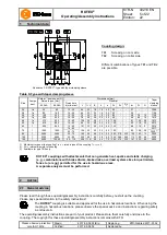
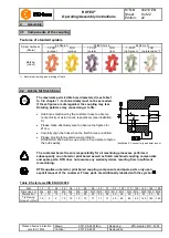
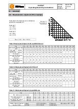
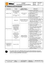
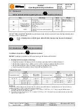
Examples of the displacement combinations
specified in illustration 15:
Example 1:
K
r
= 30 %
K
w
= 70 %
Example 2:
K
r
= 60 %
K
w
= 40 %
Illustration 15:
Combinations of
displacement
K
total
=
K
r
+
K
w
100 %
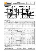
Table 9: Displacement figures for 92 and 95/98 Shore A
Size
14
19
24
28
38
42
48
55
65
75
90
100
110
125
140
160
180
Max. axial displacement
Ka
[mm]
-0.5 -0.5 -0.5 -0.7 -0.7 -1.0 -1.0 -1.0 -1.0 -1.5 -1.5 -1.5 -2.0 -2.0 -2.0 -2.5
-3.0
+1.0 +1.2 +1.4 +1.5 +1.8 +2.0 +2.1 +2.2 +2.6 +3.0 +3.4 +3.8 +4.2 +4.6 +5.0 +5.7 +6.4
Max. radial
displacement
Kr [mm] with
1500 rpm
0.17 0.20 0.22 0.25 0.28 0.32 0.36 0.38 0.42 0.48 0.50 0.52 0.55 0.60 0.62 0.64 0.68
3000 rpm
0.11 0.13 0.15 0.17 0.19 0.21 0.25 0.26 0.28 0.32 0.34 0.36 0.38
-
-
-
-
Kw [degree]
max. angular displacement
with n=1500 rpm
Kw [mm]
1.2
1.2
0.9
0.9
1.0
1.0
1.1
1.1
1.2
1.2
1.2
1.2
1.3
1.3
1.2
1.2
1.2
0.67 0.82 0.85 1.05 1.35 1.70 2.00 2.30 2.70 3.30 4.30 4.80 5.60 6.50 6.60 7.60 9.00
Kw [degree]
max. angular displacement
with n=3000 rpm
Kw [mm]
1.1
1.1
0.8
0.8
0.9
0.9
1.0
1.0
1.1
1.1
1.1
1.1
1.2
-
-
-
-
0.60 0.70 0.75 0.85 1.10 1.40 1.60 2.00 2.30 2.90 3.80 4.20 5.00
-
-
-
-
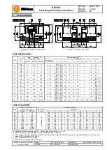
Table 10: Displacement figures for 64 Shore D
Size
14
19
24
28
38
42
48
55
65
75
90
100
110
125
140
160
180
Max. axial displacement
Ka
[mm]
-0.5 -0.5 -0.5 -0.7 -0.7 -1.0 -1.0 -1.0 -1.0 -1.5 -1.5 -1.5 -2.0 -2.0 -2.0 -2.5
-3.0
+1.0 +1.2 +1.4 +1.5 +1.8 +2.0 +2.1 +2.2 +2.6 +3.0 +3.4 +3.8 +4.2 +4.6 +5.0 +5.7 +6.4
Max. radial
displacement
Kr [mm] with
1500 rpm
0.11 0.13 0.15 0.18 0.21 0.23 0.25 0.27 0.30 0.34 0.36 0.37 0.40 0.43 0.45 0.46 0.49
3000 rpm
0.08 0.09 0.10 0.13 0.15 0.16 0.18 0.19 0.21 0.24 0.25 0.26 0.28
-
-
-
-
Kw [degree]
max. angular displacement
with n=1500 rpm
Kw [mm]
1.1
1.1
0.8
0.8
0.9
0.9
1.0
1.0
1.1
1.1
1.1
1.1
1.2
1.2
1.1
1.1
1.1
0.57 0.77 0.77 0.90 1.25 1.40 1.80 2.00 2.50 3.00 3.80 4.30 5.30 6.00 6.10 7.10 8.00
Kw [degree]
max. angular displacement
with n=3000 rpm
Kw [mm]
1.0
1.0
0.7
0.7
0.8
0.8
0.9
0.9
1.0
1.0
1.0
1.0
1.1
-
-
-
-
0.52 0.70 0.67 0.80 1.00 1.30 1.60 1.80 2.20 2.70 3.50 4.00 4.90
-
-
-
-
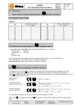
Table 11: Displacement figures for type DKM only
Size
19
24
28
38
42
48
55
65
75
90
Max. axial displacement
Ka [mm]
+1.2
+1.4
+1.5
+1.8
+2.0
+2.1
+2.2
+2.6
+3.0
+3.4
-1.0
-1.0
-1.4
-1.4
-2.0
-2.0
-2.0
-2.0
-3.0
-3.0
Max. radial displacement
Kr [mm] with n =
1500 rpm
0.45
0.59
0.66
0.77
0.84
0.91
1.01
1.17
1.33
1.48
3000 rpm
0.40
0.53
0.60
0.70
0.75
0.82
0.81
1.05
1.19
1.33
Kw [degree] max. angular
displacement with n =
1500 rpm
1.0
1.0
1.0
1.0
1.0
1.0
1.0
1.0
1.0
1.0
3000 rpm
0.9
0.9
0.9
0.9
0.9
0.9
0.9
0.9
0.9
0.9
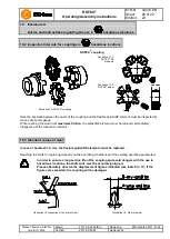
4
Assembly
4.5 Displacements - alignment of the couplings


