RADEX
®
-N
Operating/Assembly instructions
KTR-N
Sheet:
Edition:
47110 EN
22 of 31
24
Please observe protection
note ISO 16016.
Drawn:
2019-07-23 Pz/Wb
Replacing:
KTR-N dated 2018-07-17
Verified:
2019-07-26 Pz
Replaced by:
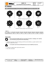
Table 11: Tightening torque of screw connections on the lamina set
Size
20
25
35
38
42
50
60
Dimension G
1
[mm]
M5
M6
M6
M8
M8
M10
M8
Tightening torque T
A
[Nm]
8.5
14
14
35
35
69
33
Size
70
80
85
90
105
115
135
Dimension G
1
[mm]
M10
M10
M12
M16
M16
M20
M24
Tightening torque T
A
[Nm]
65
65
115
280
280
550
900
Size
136 / 138 156 / 158 166 / 168 186 / 188 206 / 208 246 / 248 286 / 288
336 / 338
Dimension G
1
[mm]
M24
M27
M27
M27
M30
M36
M42
M48
Dimension G
2
[mm]
8 x M8
9 x M8
9 x M8
9 x M8
8 x M10
8 x M12
10 x M12
11 x M12
Pressure screw G
2
Tightening torque T
A
[Nm]
30
30
30
30
60
105
105
105
!
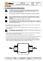
Having started up the coupling, the tightening torque of the screw connections has to be
inspected at regular maintenance intervals.
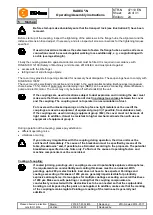
The displacement figures specified in table 12 provide for sufficient safety to compensate for external influences
like, for example, thermal expansion or foundation settling.
!
In order to ensure a long service life of the coupling and avoid dangers with the use in
potentially explosive atmospheres, the shaft ends must be accurately aligned.
Please absolutely observe the displacement figures specified (see table 12). If the figures
are exceeded, the coupling will be damaged.
The more accurate the alignment of the coupling, the longer is its service life.
If used in potentially explosive atmospheres for explosion group IIC, only half of the
displacement figures (see table 12) are permissible.
Please note:
•
The displacement figures specified in table 12 are maximum figures which must not arise in parallel. If radial,
axial and angular displacement arises at the same time, these values must be reduced (see illustration 34).
•
Please inspect with a dial gauge, ruler or feeler gauge whether the permissible displacement figures specified
in table 12 can be observed.
Angular displacements
Radial displacements
Axial displacements
Illustration 33: Displacements
4
Assembly
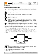
4.9 Tightening torques of screw connections on the lamina set
4.10 Displacements - alignment of the coupling


