RADEX
®
-N
Operating/Assembly instructions
KTR-N
Sheet:
Edition:
47110 EN
19 of 31
24
Please observe protection
note ISO 16016.
Drawn:
2019-07-23 Pz/Wb
Replacing:
KTR-N dated 2018-07-17
Verified:
2019-07-26 Pz
Replaced by:
!
With the assembly please make sure that the lamina sets are installed free from distortion in
axial direction. Disregarding this advice may cause damage to the coupling.
•
Clean and degrease the contact surfaces of screw connections on the flange hub, lamina set and spacer.
•
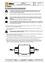
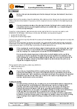
Insert the lamina sets and the spacer (see illustration 26 and 27, respectively). With type NN only 1 lamina set
is used (no spacer).
•
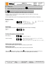
Hand-tighten the components for the time being, the fit bolts to be assembled reciprocally (see illustration 26
or 27, respectively).
•
Tighten the hexagon nuts one after the other and with several revolutions to the tightening torque specified in
table 11. Secure the dowel screw against twisting.
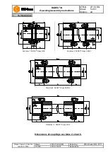
Lamina set
Illustration 26: Assembly of lamina sets, RADEX
®
-N size 20 - 70
Lamina set
Illustration 27: Assembly of lamina sets, RADEX
®
-N size 80 - 135
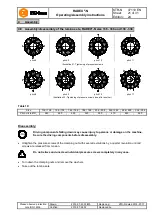
Table 9:
Size
20
25
35
38
42
50
60
70
80
85
90
105
115
135
Pitch circle Ø D
1
44
53
67
75
85
100
112
128
148
158
170
185
214
240
Disassembly:
STOP
Driving components falling down may cause injury to persons or damage on the machine.
Secure the driving components before disassembly.
•
Unscrew the hexagon nuts and remove along with the fit bolts and disks.
•
Take out the lamina sets.
4
Assembly
4.7 Assembly/disassembly of the lamina sets, RADEX
®
-N size 20 - 135

