RADEX
®
-N
Operating/Assembly instructions
KTR-N
Sheet:
Edition:
47110 EN
16 of 31
24
Please observe protection
note ISO 16016.
Drawn:
2019-07-23 Pz/Wb
Replacing:
KTR-N dated 2018-07-17
Verified:
2019-07-26 Pz
Replaced by:
Table 8: Tightening torques of clamping screws
Size
35
38
42
50
60
70
80
85
90
105
115
135
Clamping screws
M5
M6
M6
M8
M8
M8
M10
M12
M12
M12
M12
M16
Tightening torque T
A
[Nm]
8.5
14
14
35
35
35
69
120
120
120
120
295
!
Having started up the coupling the tightening torques of the screws have to be inspected
during the usual inspection intervals.
Disassembly:
STOP
Driving components falling down may cause injury to persons or damage on the machine.
Secure the driving components before disassembly.
•
Unscrew the clamping screws evenly one after another. During every revolution every screw may only be
unscrewed by half a turn. Unscrew all clamping screws by 3 - 4 pitches.
•
Remove the screws located next to the extraction threads and screw them into the respective extraction
threads until they fit.
•
The clamping ring is released by tightening the screws in the extraction threads evenly gradually and
crosswise.
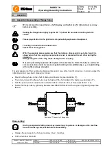
Illustration 19: Disassembly of clamping ring hub type 6.0
Illustration 20: Disassembly of clamping ring hub type 6.5
•
In case of a repeated assembly the hub bore and shaft have to be cleaned and afterwards lubricated with a
thin-bodied oil (e. g. Castrol 4 in 1 or Klüber Quietsch-Ex). The same applies for the taper surfaces of clamping
ring hub and clamping ring.
!
If these hints are not observed, the operation of the clamping ring hub may be affected.
4
Assembly
4.4 Assembly/disassembly of clamping ring hubs


