RADEX
®
-N
Operating/Assembly instructions
KTR-N
Sheet:
Edition:
47110 EN
17 of 31
24
Please observe protection
note ISO 16016.
Drawn:
2019-07-23 Pz/Wb
Replacing:
KTR-N dated 2018-07-17
Verified:
2019-07-26 Pz
Replaced by:
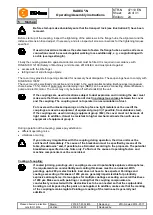
If the coupling is supplied with a transportation lock (optionally), the
following has to be observed:
Illustration 21: Transport lock
!
The spacer sleeves (steel) have to be removed for
further assembly and operation (see illustration
21).
•
Disassemble the transportation screws and spacer sleeves.
If the coupling is supplied with limitation for axial clearance
(optionally), the following has to be observed:
•
Before mounting the spacer, remove the screws and sleeves for
limitation of axial clearance.
•
Having mounted the spacer completely, re-assemble the screws
and sleeves for limitation of axial clearance (see illustration 22).
Please observe the axial clearance S as per dimension sheet.
•
Secure the screws against working loose by means of a high-
strength adhesive (e. g. omniFIT 230M or Loctite 2701).
Illustration 22: Limitation of axial clearance
!
Please take into account whether a limitation for axial clearance with two nylon sleeves per
screw or one transportation lock with one steel sleeve per screw was installed (see
illustration 21 and 22).
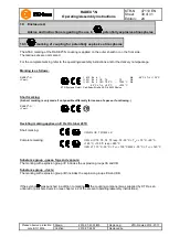
Marking of balancing (optional)
•
With the assembly of the spacer please observe the correct alignment of the marking for balancing. The
marking for balancing X (Y) of the hub, as an example, must be flush with the marking for balancing X (Y) of
the spacer (see illustration 23).
Illustration 23: Alignment of spacer
4
Assembly
4.5 General advice for assembly of spacer


