background image


RADEX

®

-N 

Operating/Assembly instructions 

KTR-N 
Sheet: 
Edition: 

47110 EN 
13 of 31 
24 


Please observe protection 

note ISO 16016. 

Drawn: 

2019-07-23 Pz/Wb 

Replacing: 

KTR-N dated 2018-07-17 

Verified: 

2019-07-26 Pz 

Replaced by: 


STOP 


The maximum permissible bore diameters d (see 
chapter 1 - technical data) must not be exceeded.  
If these figures are disregarded, the coupling may 
tear. Rotating particles may cause danger to life. 


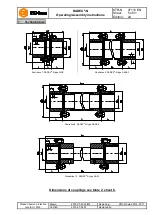
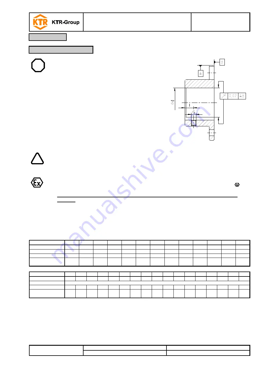
Illustration 16: Concentricity and axial run-out 

  Bores of flange hubs machined by the customer have to observe 

concentricity or axial runout, respectively (see illustration 16). 

  Please make absolutely sure to observe the figures for Ø d

max

  Carefully align the flange hubs when the finish bores are drilled. 

  Please provide for a setscrew according to DIN EN ISO 4029 with 

a cup point or an end plate to fasten the flange hubs axially.


The customer bears the sole responsibility for all machining processes performed 
subsequently on unbored or pilot bored as well as finish machined coupling components 
and spare parts. KTR does not assume any warranty claims resulting from insufficient 
remachining.


KTR supplies unbored or pilot bored coupling components and spare parts only upon 
explicit request of the customer. These parts are additionally marked with the symbol 


Reference to unbored resp. pilot bored coupling components with explosion protection 
marking: 

Basically the company KTR supplies couplings resp. coupling hubs with explosion protection 
marking as an unbored or pilot bored type only on explicit request of the customer. The prerequisite 
is a declaration of exemption submitted by the customer assuming any responsibility and liability for 
remachining performed properly.


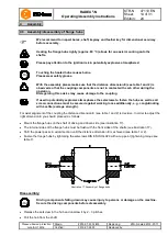
Table 7: Setscrew DIN EN ISO 4029 

Size 

20 

25 

35 

38 

42 

50 

60 

70 

80 

85 

90 

105 

115 

M5 

M5 

M6 

M6 

M8 

M8 

M8 

M10 

M10 

M10 

M12 

M12 

M12 

15 

15 

20 

20 

20 

20 

20 

25 

25 

30 

30 

Number z 

Tightening torque T

A


[Nm] 

4.8 

4.8 

10 

10 

10 

17 

17 

17 

40 

40 

40 


Size 

135 

136 

156 

166 

186 

206 

246 

286 

336 

138 

158 

168 

188 

208 

248 

288 

338 

M20  M12  M12  M16  M16  M16  M20  M20  M24  M12  M12  M16  M16  M16  M20  M20  M24 

As specified by the customer 

Number z 

Tightening torque T

A


[Nm] 

140 

40 

40 

80 

80 

80 

140 

140 

240 

40 

40 

80 

80 

80 

140 

140 

240 


Assembly 

4.2  Advice for finish bore 

Содержание RADEX NANA 2

Страница 1: ...te ISO 16016 Drawn 2019 07 23 Pz Wb Replacing KTR N dated 2018 07 17 Verified 2019 07 26 Pz Replaced by RADEX N Steel lamina couplings types NN NANA 1 to 4 NENA 1 and 2 NENE 1 NNZ NNW according to dir...

Страница 2: ...f flange hubs 14 4 4 Assembly disassembly of clamping ring hubs 15 4 5 General advice for assembly of spacer 17 4 6 Vertical assembly disassembly 18 4 7 Assembly disassembly of the lamina sets RADEX N...

Страница 3: ...z Wb Replacing KTR N dated 2018 07 17 Verified 2019 07 26 Pz Replaced by Illustration 1 RADEX N type NN Illustration 2 RADEX N type NANA 1 Illustration 3 RADEX N type NANA 2 Illustration 4 RADEX N typ...

Страница 4: ...178 18 90 100 85 132 119 210 80 175 15 300 140 251 91 233 73 166 6 184 24 105 110 90 147 128 225 90 200 20 340 160 281 101 263 83 186 6 204 24 115 120 100 163 145 265 100 223 23 370 170 309 109 288 8...

Страница 5: ...n note ISO 16016 Drawn 2019 07 23 Pz Wb Replacing KTR N dated 2018 07 17 Verified 2019 07 26 Pz Replaced by Illustration 7 RADEX N type NNZ Illustration 8 RADEX N type NANA 3 Illustration 9 RADEX N ty...

Страница 6: ...5 150 166 170 225 350 165 186 190 250 380 185 206 210 275 420 200 246 245 320 500 240 286 290 383 567 280 336 340 445 660 330 138 135 180 300 135 158 150 195 325 150 168 170 225 350 165 188 190 250 38...

Страница 7: ...7500 21000 26250 45000 Max speed n rpm 5400 5000 4300 3700 3800 3500 3300 3000 2800 2300 Size 286 336 138 158 168 188 208 248 288 338 Torque Nm TKN 150000 210000 23000 33000 45000 56000 70000 120000 2...

Страница 8: ...ure to read through and observe the following safety indications All operations on and with the coupling have to be performed taking into account safety first Please make sure to switch off the power...

Страница 9: ...rsional vibrations are e g drives with diesel engines piston pumps piston compressors etc If requested KTR will perform the coupling selection and the torsional vibration calculation The couplings sup...

Страница 10: ...Washer 3 Spacer 7 see table 6 Hexagon nut clamping nut 4 see table 6 Dowel screw 8 2 Setscrew DIN EN ISO 4029 1 Design as clamping ring hub frictionally engaged shaft hub connection on request Illustr...

Страница 11: ...le 6 Dowel screw 8 2 Setscrew DIN EN ISO 4029 1 Design as clamping ring hub frictionally engaged shaft hub connection on request Illustration 13 RADEX N type NNZ Components of RADEX N type NANA 4 Comp...

Страница 12: ...aft hub connection on request Illustration 15 RADEX N type NNW Table 6 Number of single parts Size 20 25 35 38 42 50 60 70 80 85 Fit bolt item 4 1 4 4 4 4 4 4 6 6 6 6 Distance sleeve item 5 1 4 4 4 4...

Страница 13: ...warranty claims resulting from insufficient remachining KTR supplies unbored or pilot bored coupling components and spare parts only upon explicit request of the customer These parts are additionally...

Страница 14: ...to fasten the hubs as well as all screw connections must be secured against working loose additionally e g conglutinating with Loctite average strength For axial alignment of the coupling the distanc...

Страница 15: ...e table 1 and 2 is decisive In order to set the right dimension E you should proceed as follows Clean and degrease the hub bores and shafts afterwards lubricate with a thin fluid oil e g Castrol 4 in...

Страница 16: ...screw the clamping screws evenly one after another During every revolution every screw may only be unscrewed by half a turn Unscrew all clamping screws by 3 4 pitches Remove the screws located next to...

Страница 17: ...Having mounted the spacer completely re assemble the screws and sleeves for limitation of axial clearance see illustration 22 Please observe the axial clearance S as per dimension sheet Secure the sc...

Страница 18: ...tion 24 and 25 as an alternative The internal sides of the flange hub on top or centering surface of the flange hub at the bottom must be flush with the front sides of the shafts see illustration 24 a...

Страница 19: ...e time being the fit bolts to be assembled reciprocally see illustration 26 or 27 respectively Tighten the hexagon nuts one after the other and with several revolutions to the tightening torque specif...

Страница 20: ...under the screw head The pressure screws in the clamping nut must not protude on the pressure side see illustration 29 All components must be superimposed without any gap Afterwards turn back the clam...

Страница 21: ...168 186 188 206 208 246 248 286 288 336 338 Pitch circle D1 240 260 290 320 350 410 480 550 Disassembly STOP Driving components falling down may cause injury to persons or damage on the machine Secure...

Страница 22: ...to compensate for external influences like for example thermal expansion or foundation settling In order to ensure a long service life of the coupling and avoid dangers with the use in potentially ex...

Страница 23: ...Type NN NANA1 NANA2 Kw angular 1 20 0 60 1 2 1 0 0 2 1 0 25 0 80 1 6 1 0 0 2 1 0 35 1 00 2 0 1 1 0 3 1 0 38 1 20 2 4 1 2 0 3 1 0 42 1 40 2 8 1 2 0 4 1 0 50 1 60 3 2 1 5 0 4 1 0 60 1 00 2 0 1 5 0 8 1 0...

Страница 24: ...volume between the cover and the coupling The coupling must not operate in an accumulation of dust For covers with unlocked openings on the top face no light metals must be used if the couplings are...

Страница 25: ...Elimination Different operating noise and or vibrations occuring Misalignment none 1 Set the unit out of operation 2 Eliminate the reason for the misalignment e g loose foundation bolts breaking of t...

Страница 26: ...2 Disassemble the coupling and remove remainders of the steel lamina sets 3 Inspect coupling components and replace coupling components that have been damaged 4 Insert steel lamina sets assemble coupl...

Страница 27: ...g and driven side settle during the course of load inspect the alignment of the coupling and re align the coupling if necessary If some individual laminas are broken the lamina sets of the coupling ha...

Страница 28: ...o 230 C 250 C T3 40 C to 175 C 195 C T4 40 C to 110 C 130 C T5 40 C to 75 C 95 C T6 40 C to 60 C 80 C Explanation The maximum surface temperatures each result from the maximum permissible ambient or o...

Страница 29: ...ndable to replace the lamina sets find out the cause according to the table Breakdowns if possible The maintenance intervals must be adjusted to the modified operating parameters without fail 2G 2D Ga...

Страница 30: ...f not possible differently for reason of space or functioning RADEX N Year Deviating marking applies until 31st October 2019 Short marking II 2GD c IIC T X I M2 c X Complete marking II 2G c IIC T6 T5...

Страница 31: ...requirements according to enclosure II of directive 2014 34 EU The coupling described in here complies with the specifications of the following standards rules DIN EN ISO 80079 36 DIN EN ISO 80079 37...

Отзывы: