RADEX
®
-N
Operating/Assembly instructions
KTR-N
Sheet:
Edition:
47110 EN
20 of 31
24
Please observe protection
note ISO 16016.
Drawn:
2019-07-23 Pz/Wb
Replacing:
KTR-N dated 2018-07-17
Verified:
2019-07-26 Pz
Replaced by:
!
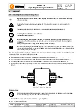
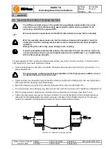
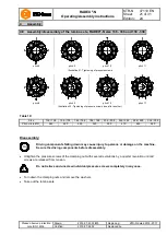
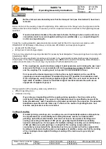
With the assembly please make sure that the lamina sets are installed free from distortion in
axial direction. Disregarding this advice may cause damage to the coupling.
•
Clean and degrease the contact surfaces of screw connections on the flange hub, lamina set and spacer as
well as the threads of the clamping nut and dowel screw.
•
Insert the lamina sets and the spacer (see illustration 28). With type NN only 1 lamina set is used (no spacer).
•
Hand-tighten the components for the time being, the dowel screws to be assembled reciprocally (see
illustration 28). With size 156 and 158 use a washer under the screw head.
•
The pressure screws in the clamping nut must not protude on the pressure side (see illustration 29).
!
All components must be superimposed without any gap.
•
Afterwards turn back the clamping nut until there is a gap of 1 - 2 mm (see illustration 29).
•
Hand-tighten the pressure screws marked in illustration 31.
•
Tighten these screws (see illustration 31) at half the tightening torque according to table 11 and afterwards at
the full tightening torque according to table 11.
•
Now tighten all pressure screws one after another and with several revolutions until all screws have achieved
the full tightening torque (see illustration 32).
!
The pressure screws must not bear on the heads after assembly (see illustration 30).
•
All clamping nuts have to be mounted as per the aforementioned process.
Lamina set
Illustration 28: Assembly of the lamina sets, RADEX
®
-N size 136 - 336 and 138 - 338
Illustration 29
Illustration 30
4
Assembly
4.8 Assembly/disassembly of the lamina sets, RADEX
®
-N size 136 - 336 and 138 - 338


