background image

Mounting axes 

page 53 


7.7.10


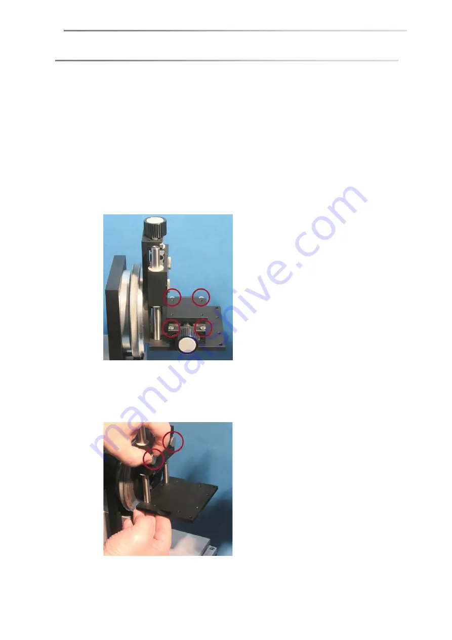
Mounting the ST13 miniature sample table (optional) 

The optionally available ST13 sample table for positioning samples horizontally can 
be mounted in two directions: 


forwards with the adjusting screw for positioning perpendicular to the optical 
axis 


to the right with the adjusting screw for positioning along the optical axis 

Adjusting screw forwards 


Fix the table with the four hexagon socket screws supplied. 


Adjusting screw right 

1.  Loosen the two knurled screws and remove the sample stage from the holder 

together with the mount. 

Содержание DSA100

Страница 1: ...Drop Shape Analyzer DSA100 Installation and Operation V1 45 KRÜSS GmbH Hamburg 2004 2014 ...

Страница 2: ......

Страница 3: ...r driver installation 12 4 2 2 Frame grabber driver for CF3200 3201 13 4 2 3 Frame grabber driver for CF3220 21 13 4 2 4 IEEE 1394 driver for CF31 3216 18 5 Setting up 21 5 1 Opening the transport packing and checking the scope of supply 21 5 2 Transport 21 5 3 Location and ambient conditions 21 5 4 Levelling the instrument 22 5 5 Power supply power switch 23 5 6 Connecting the computer 23 5 6 1 C...

Страница 4: ...g with the Tilting Table 44 7 6 2 Weight and dimensions not mounted 45 7 6 3 Mounting the tilting table 45 7 7 PA3240 internal tilting table 47 7 7 1 Overview 47 7 7 2 Note 47 7 7 3 Mounting 47 7 7 4 Connecting the tilting table 49 7 7 5 Centring the tilting table in the optical axis 49 7 7 6 Levelling the tilting table 50 7 7 7 Adjusting the height of the sample stage 51 7 7 8 Fitting the holding...

Страница 5: ...ert gas connector 72 11 5 5 TC40 only Power supply Communication 73 11 6 Preparing the measurement 74 11 6 1 Introducing the sample 74 11 6 2 Positioning the chamber 75 11 6 3 Positioning the sample perpendicular to the optical axis 75 11 7 Additional components 76 11 7 1 Base plate attachment for flat samples 76 11 7 2 Heat conducting hood 76 11 8 TC40 only Setting and reading off the measuring t...

Страница 6: ...if ordered afterwards 92 IIIa Safety notes 92 IIIb Procedure 93 IV Mounting steps for a multi dosing unit if ordered afterwards 96 IVa Assembling the syringe driver unit s 96 IVb Assembling the syringe revolver 102 V Addresses and mounting of the electronic module EM3201 105 Va Overview 105 Vb Slots and addresses 106 Vc Mounting 107 VI Test liquids for multi dosing unit DS3222 3228 111 VIIFor DSA1...

Страница 7: ...hich have already been used for handling hazardous materials SPAC SPAC SPAC SPAC Do not use the DSA100 if the unit is obviously damaged SPAC SPAC SPAC SPAC Disconnect the DSA100 from the power supply immediately if there is any damage to the electronics if liquids are spilled over the DSA100 or if there is an escape of tempering medium SPAC SPAC SPAC SPAC Handle all glass parts and optical parts w...

Страница 8: ...th the unit KRÜSS customer support will advise you on the necessary scope of the shipment Remove liquids e g samples temperature control liquid completely from the instrument and the accessories Clean the unit or accessories before dispatch This applies particularly if there is contamination due to hazardous substances Use the original packaging to pack the instrument or accessories If you no long...

Страница 9: ...page www kruss de contains the complete manual SPAC SPAC SPAC SPAC 1 5 Note concerning images The images of some components show the mounting procedure and use for a KRÜSS instrument DSA30 The procedure for the DSA100 is identical in these cases SPAC SPAC SPAC SPAC 1 6 Technical customer service If problems should occur when working with your KRÜSS product please consult the technical customer sup...

Страница 10: ... the download section of our homepage www kruss de SPAC SPAC SPAC SPAC The system is characterized by its high degree of flexibility All the components movement axes video system dosing unit environmental chambers can be easily exchanged or extended All intermediate stages are possible from fully manual operation up to PC control of all the components Possible uses of the DSA100 The DSA100 measuri...

Страница 11: ... data on liquids that can be directly linked to the measuring data Comfortable data management and documentation Extendable at any time with components such as environmental chambers automatic axes software controlled optics or multiple dosing units with up to 8 syringes ...

Страница 12: ...rabber and shown on the monitor The DSA software contains time proven tools for analysing the drop image with whose help it is possible to calculate the contact angle surface energies and surface tensions In principle the DSA100 consists of three components The sample table with up to three mobile axes or a rotating wafer table The video system with camera optical system prism light source and ape...

Страница 13: ...ng the computer housing Touching the expansion board when the body is charged electrostatically can damage electronic components Before touching the board discharge yourself for example by touching a metallic part of the panel Mounting the board must be carried out before driver installation and before installing the DSA software If necessary obtain the help of a computer specialist 1 Switch off t...

Страница 14: ... and Vista the frame grabber board can be damaged if the automatic driver update via internet is activated Deactivate the automatic driver installation before assembling the board see below Deactivating the automatic driver update 1 Select the Control Panel in the Windows start menu and open the configuration menu System 2 Select the tab sheet Hardware and click on Windows Update ...

Страница 15: ...SA3 DSA4 CD After installing the frame grabber the DSA1 DSA3 DSA4 software can be installed Further information is given in the DSA1 DSA3 DSA4 manual Let the assistant search for the drivers on the DSA1 DSA3 DSA4 CD The drivers will be installed automatically after confirmation with OK SPAC SPAC SPAC SPAC 4 2 3 Frame grabber driver for CF3220 21 First close all running programs several re boots ar...

Страница 16: ...e DSA4 software with the help of prepared parameter files DSA4 manual chapter about high speed cameras 1 After switching on the computer terminate the Windows hardware assistant 2 Insert the DSA3 CD ROM Select the folder Cameras PxH PFRemote and start the program PFInstallerxx exe Continue the installation with Next xxx stands for the version number inside the filename 3 Confirm your license agree...

Страница 17: ... can be created on the desktop or in the Windows quick launch bar Confirm your selection with Next 9 Click on Install to carry out the installation 10 Before finishing the setup program recommends reading two information texts Conclude the installation with Finish Step 2 Frame grabber driver installation 1 Select the folder CF3220 on the DSA4 CD and start the program setup exe 2 Confirm the instal...

Страница 18: ...t the Windows Logo Test was not passed and continue with the installation 7 Confirm the reboot of the computer at the end of the installation Step 3 Installation of the Mil Lite patch 1 Select the folder CF3220 Mil Lite Patch on the DSA4 CD and start the containing exe program 2 Click on Next in the welcome window to start the installation A text pops up and informs you about the changes 3 Confirm...

Страница 19: ...e Confirm this message with OK The frame grabber gets updated automatically If no message appears no update is necessary In this case just terminate the program Intellicam 3 After the upgrade the computer switches off automatically Reboot the computer Step 5 Reducing the hardware acceleration 1 Start the program MilConfig from the start menu folder Matrox Imaging Tools 2 Select the Video Hardware ...

Страница 20: ... DSA4 CD 2 Open the folder SUPPORT CFxx1x AxF AVT IEEE1394 Open the containing folder named after the version number of the installation program Start the program AVTFirePackage_xxx exe xxx stands for the version number inside the filename 3 Click Next in the welcome window 4 A warning message appears that installing the AVT driver blocks the IEEE 1394 interface for other drivers Click on Next ...

Страница 21: ...AVT software to be installed shall be created on the desktop Install startmenu items Determine if AVT items in the Windows start menu shall appear for the Current user only or for All users 6 Click on Install to start the installation If necessary confirm the continuation of the installation in the warning message Windows Logo Test 7 Select the option Run Driver Installer on the last page Click on...

Страница 22: ... 20 Computer system 8 A Microsoft driver is displayed in the Driver Installer Select the option Intek 1334 Bus Driver in the hidden drop down menu in the column Switch To Click on Apply SPAC SPAC SPAC SPAC ...

Страница 23: ...l components are fixed SPAC SPAC SPAC SPAC Transport the DSA100 with the help of a trolley Hold the DSA100 firmly during transportation SPAC SPAC SPAC SPAC For lifting hold the DSA100 from both sides under the base plate SPAC SPAC SPAC SPAC Do not hold the instrument at the illumination a dosing unit or an axis for lifting SPAC SPAC SPAC SPAC SPAC SPAC SPAC SPAC 5 3 Location and ambient conditions...

Страница 24: ...vibration free base Check if the base is level using a bubble level or spirit level SPAC SPAC SPAC SPAC 5 4 Levelling the instrument After positioning the DSA100 must be levelled For levelling two spirit levels are located on the bottom of the standard sample table support 1 Remove the sample table adapter from the sample table 2 Remove the two clips if present from the sample table support 3 Turn...

Страница 25: ...e drives if present move to their zero positions for initialisation When the instrument is switched on the LED on the front panel lights up to show an intensive blue when the instrument is switched off it is still weakly lit up SPAC SPAC SPAC SPAC 5 6 Connecting the computer The computer is to be connected to the RS232 connection Serial PC at the rear side of the DSA100 A corresponding cable is wi...

Страница 26: ...to the adapter Switch on the DSA100 Afterwards always use the same USB port of the computer if possible Otherwise the serial port assignment Chapter 5 6 2 must be changed 3 Select manual for the driver search when carrying out the driver installation 4 Select the folder SUPPORT KA10 Driver Windows 7 0 on the DSA4 CD 5 Click on OK Driver installation starts 5 6 2 Port assignment After the start of ...

Страница 27: ... opens Select the occupied COM port from the drop down menu marked above SPAC SPAC SPAC SPAC 5 7 Protective glass A protective glass to be attached to the front panel is supplied with the instrument The protective glass prevents accidental contact with the needle tip to avoid injury or poisoning risks This protective glass should only be removed when conversion work is being carried out ...

Страница 28: ...8 Connecting a temperature sensor On the base of the illumination module there are two connectors for connecting a temperature sensor Connect the temperature sensor to the rear socket the following image shows the rear side ...

Страница 29: ...of the computer Use the supplied BNC cable CF3220 Connect the cable with the Camera Link plug coming from the DSA100 panel to the connection Channel 0 of the frame grabber board IEEE 1394 cameras Connect the IEEE 1394 connector at the rear side of the DSA100 housing to the right hand connection of the IEEE 1394 interface board of the computer Only use the delivered IEEE 1394 interface board for co...

Страница 30: ...til it clicks into position The prism can be tilted in order to change the viewing angle of the drop The advantage of this arrangement is that the position of the drop image does not alter and the image itself is not distorted The tilting angle is regulated by using the rotary knob beside the prism When the instrument is switched on the scale on the left hand side of the housing shows the set tilt...

Страница 31: ...le ST3230 3280 is installed Standard prism Prism for large samples Use the standard prism in any other case With the prism for large samples measurements must be carried out with a view angle of at least 2 6 3 Illumination aperture The sample is illuminated with a software controlled illumination DSA1 DSA3 DSA4 software manual A manual aperture is additionally provided to measure small contact ang...

Страница 32: ...page 30 Optical components Inserting the aperture Slide the aperture from below into the gap between the illumination and the dosing unit fixture ...

Страница 33: ...anual or software controlled can be assembled on the frame Setup with one vertical axis and two horizontal axes Base Spacer x Axis y Axis z Axis lifting table Sample table Alternative setups Not mounted x or y axes are replaced by an additional spacer respectively Instead of an x axis a rotating table wafer table can be mounted The wafer table is mounted onto a z axis Instead of a sample table an ...

Страница 34: ...cer Mount the spacer on top of the already mounted spacer using the three hexagon socket screws provided In rare cases the spacer must be mounted on the base plate of the DSA100 7 2 2 Replacing an axis with a spacer If an axis must be removed or replaced by a spacer proceed as follows 1 Move the installed x or y axis out of the center to that the fixing screws are released With software controlled...

Страница 35: ...from the spacer SPAC SPAC SPAC SPAC 7 3 Mounting axes Safety note The axes are fixed at four edges with one screw each Tighten up the screws in rotating order to achieve uniform stress and avoid tilting Fixing strips Each axis is either screwed onto a spacer or onto another axis To mount an axis fixing strips are required as follows Two strips without threads for attaching an axis to a spacer Two ...

Страница 36: ...y be required for the occasion of conversions 7 3 1 Mounting an x or y axis on a spacer 1 Place the axis on the built in spacer and hold it firmly The axis should be positioned so that the spacer is located below the centre of the range of movement of the axis 2 Place the non threaded fixing strips on the spacer so that the cramping edges fit inside the ridges of the axis 3 Slide the strip along t...

Страница 37: ...so that the cramping edges fit inside the ridges of the x axis Hold the strip firmly 3 Place two non threaded fixing strips with their cramping edges inside the ridges of the y axis Slide the strips so that the openings on the upper strip coincide with threaded openings of the lower fixing strip Fix the strips with two screws lightly so that the axis can still slide about 4 Treat the other side of...

Страница 38: ...he z axis until the openings of the z axis coincide with the openings in the strip 3 Fix the strip lightly so that the axis can still slide about 4 Fix the second strip in the same way 5 Slide the axis to the central position above the lower axis 6 Screw down the strips with four screws SPAC SPAC SPAC SPAC 7 4 Connecting software controlled axes The connections for the axes Axis 1 to Axis 4 are lo...

Страница 39: ...afer table or a tilting table can be connected to any of ports 1 3 and 4 The axes are recognized automatically The number of connection cables supplied corresponds to the number of software controlled axes that have been ordered The length of the cables to be used for each axis depends on the moving ranges of the axis ...

Страница 40: ... the prism and keep it in a safe place when carrying out the assembly work 1 If software controlled axes are installed then switch on the computer and start the DSA software 2 With manual axes wind the axis to the back until the screws are exposed With software controlled axes Select the register card Axis respectively Axes in the Device Control panel DSA1 DSA3 DSA4 Select the y axis with the butt...

Страница 41: ...g strips and screws Remove the attachment screws for the y axis 3 mm allen wrench Hold the y axis firmly so that it cannot fall to the ground 6 Screw off the remaining x axis in the same manner 7 Replace the currently assembled spacer with the 49 mm spacer 8 Place two non threaded fixing strips on the spacer y direction without fastening them down Now place the y axis on the spacer so that the gro...

Страница 42: ...e of the range of movement of the axis 10 Fix the strips Tighten up the screws in sequence to achieve uniform stress and avoid tilting 7 5 2 Mounting a wafer table ST3220 3270 Place the wafer table on the sample table The wafer table must be attached with four hexagon socket screws 4 X 8 mm Rotate the wafer table manually and use the gap in order to screw in the screws ...

Страница 43: ...When the standard prism is installed the rotating sample table can collide with the prism and damage it Exchange the standard prism with the smaller prism for large samples Standard prism Prism for large samples For removing and inserting a prism please read Chapter 6 2 Procedure The prism must be adjusted to a tilting angle of 2 for sessile drops Chapter 6 2 The rotating sample table ST3230 3280 ...

Страница 44: ...ive the axis to the front position For software controlled y axis Connect the y axis to the port AXIS 2 of the rear panel of the DSA100 and switch on the DSA100 The y axis initializes and drives to the front position automatically 5 Loosen the four screws that fix the y axis so that the whole y axis can slide forward and backward manually 6 Rotate the sample table so that the maximum length is ali...

Страница 45: ...om the front side but only if there is sufficient space behind the DSA100 8 Fix the y axis when the position is adjusted 9 With the software controlled rotating sample table Switch off the DSA100 Connect the rotating sample table with one of the ports AXIS1 AXIS3 or AXIS4 on the rear panel of the DSA100 Switch on the DSA100 again Close the DSA software and then start it up again Call up the menu c...

Страница 46: ...ms are securely fastened and remove any objects lying on the instrument WARNING Risk of injury from unexpectedly rapid Tilting Table movement If high movement speeds are set for the control of the axes then an unexpectedly rapid movement of the Tilting Table could cause injuries Before using the Tilting Table set the movement speed for the axes to medium or slow DSA software manual CAUTION Risk fr...

Страница 47: ... step do not exceed this maximum angle Do not operate the tilting table in case of an installed high temperature dosing system DS3241 7 6 2 Weight and dimensions not mounted Weight 33 1 Kg Dimensions W D H 1190 400 550 mm 7 6 3 Mounting the tilting table Assembling a tilting table should be carried out with three persons 1 Turn the DSA100 aside Four threaded holes are driven into the bottom 2 Unsc...

Страница 48: ...ur fixing screws Loosen these screws three turns counter clockwise as described on the signs at the tilting table 6 The Emergency Stop button is pressed after delivery Turn the button clockwise to release it 7 Connect the port on the rear side of the tilting table with one of the ports AXIS 1 3 or 4 at the rear panel of the DSA100 Port AXIS 2 is reserved for the y axis SPAC SPAC SPAC SPAC ...

Страница 49: ...nts with a tilting table the camera view angle must be set to 0 Chapter 6 2 SPAC SPAC SPAC SPAC 7 7 3 Mounting 1 Remove all installed axes and spacers 2 Fit the z axis PS3205 or PS3250 for heavy sample tables on the base plate of the instrument The PA3240 tilting table must not be fitted on a standard PS3201 PS3202 z axis Height adjustment fine Height adjustment coarse Base plate fixed on z axis S...

Страница 50: ...turns The strips should sit loosely but not be able to be removed 4 The tilting table must be mounted so that the sample rest is on the lamp side of the instrument Slide the tilting table on the platform of the z axis so that the clamping edges engage in the grooves in the base plate of the tilting table Hold the tilting table firmly and fix it by tightening the four screws z axis platform Fixing ...

Страница 51: ...Centring the tilting table in the optical axis 1 Set the tilting angle of the camera to 0 Chapter 6 2 2 Switch on the DSA100 and start the DSA1 DSA3 DSA4 software 3 Feed the centring device into the opening from the sample table side 4 Focus on the printed scale inside the centring device 5 The scale is calibrated in mm Adjust the zoom so that the recorded field of view is between 5 and 7 mm high ...

Страница 52: ...he screws Vertical alignment Move the tilting table to the required position with the help of the z axis height adjuster After this do not change the position of the z axis again The surface height is adjusted with the help of the tilting table sample stage 7 7 6 Levelling the tilting table Setting the tilting table to the starting position Select the Axes tab in the CPanel Select the Tilting Tabl...

Страница 53: ...described in Chapter 5 4 7 7 7 Adjusting the height of the sample stage Coarse adjustment 1 Hold the sample stage firmly from below and loosen the two knurled screws 2 Slide the sample stage to the required height 3 Retighten the two knurled screws Fine adjustment Fine adjustment is carried out using the top adjusting screw ...

Страница 54: ...es in the corners of the sample table rest SPAC SPAC SPAC SPAC 7 7 9 Fitting spacers for the protective glass If the protective glass is fitted without spacers the tilting table can come into contact with the protective glass Place the two spacers on the pins of the protective glass Place the protective glass with the spacers on the magnetic holder on the front of the DSA100 SPAC SPAC SPAC SPAC ...

Страница 55: ...wo directions forwards with the adjusting screw for positioning perpendicular to the optical axis to the right with the adjusting screw for positioning along the optical axis Adjusting screw forwards Fix the table with the four hexagon socket screws supplied Adjusting screw right 1 Loosen the two knurled screws and remove the sample stage from the holder together with the mount ...

Страница 56: ...e 54 Mounting axes 2 Fix the table on the sample stage with the four hexagon socket screws supplied 3 Slide the sample stage mount back into the holder Retighten the two knurled screws SPAC SPAC SPAC SPAC ...

Страница 57: ... which must be inserted in the fixture The inner walls of the disposable syringes may be wetted with silicone oil as lubricant 1 Take a syringe out of the packaging and pull out the plunger 2 Remove the rubber attachment from the syringe plunger and place it on the metal syringe plunger with setscrew 3 Rotate the plunger upward and push it into the disposable syringe 4 Rotate the syringe and slide...

Страница 58: ...ed to fasten the stand of the manual dosing unit to the attachment plate 2 Assemble the syringe holder as shown in the following illustration 3 Place the syringe holder with the two pins in the holes of the dosing stand and fasten it to the stand with the screw SPAC SPAC SPAC SPAC attachment plate Syringe adaptor horizontal alignment ...

Страница 59: ... Click on the button if necessary 2 Move the needle to a position between the camera and the light source SPAC SPAC SPAC SPAC 3 Set the illumination zoom and focus for the needle image The needle should be in focus and take about one tenth of the image width For software controlled optics this is carried out in the tab Imaging DSA1 respectively O Con DSA3 DSA4 software manual 4 Use the setscrew on...

Страница 60: ...ing Unit DS3210 and the belonging electronic module EM3201 9 1 Mounting the dosing unit 1 Attach the stand of the dosing unit to the fixing plate of the DSA100 using the four set screws provided 2 Connect the right hand plug of the dosing carriage to the left hand plug on the upper side of the DSA100 housing SPAC SPAC SPAC SPAC Fixing plate Horizontal alignment ...

Страница 61: ...he disposable syringes may be wetted with silicone oil as lubricant Bleeding the syringe The syringe can be easily filled in the fitted state To do this it must first be filled and bled so that there is no air in the syringe when it is filled later 1 Fit a needle to the syringe 2 Fill the syringe with the test liquid 3 Hold the syringe upright and force residual air out of the syringe and needle F...

Страница 62: ...ed in Step 1 SPAC SPAC SPAC SPAC 9 3 Adjusting the dosing unit The dosing unit must be adjusted with respect to the camera so that the middle horizontal needle position is in the middle of the recorded image 1 Start the DSA software The camera button in the toolbar must be shown as being pressed live image Click on the button if necessary SPAC SPAC SPAC SPAC 2 Select the tab Needle Pos DSA1 respec...

Страница 63: ...e middle position in the video image SPAC SPAC SPAC SPAC 9 4 Restricted software options Some functions of the DSA3 DSA4 software are restricted to multi dosing units and cannot be used for DS3210 Due to the simplified syringe control of the DS3210 no information about the current syringe driver position is transferred to the software Therefore the filling level display and the Auto Refill functio...

Страница 64: ...t are not listed there SPAC SPAC SPAC SPAC 10 1 Initialising the syringe drives CAUTION Risk from escaping liquids toxic highly flammable or corrosive If syringes are already inserted and filled liquid which escapes during the initialization can lead to a risk depending on the hazard class of the liquid Empty the syringes and lead the liquid into a waste container before starting the initializatio...

Страница 65: ...he first syringe in the DSA1 DSA3 DSA4 software Chapter 10 1 2 In order to remove air from the refill tube the dosing valve must be switched to channel the liquid from the syringe to the refill tube For DSA1 Select the tab sheet Refill from the Device Control panel Click on the Valve Position for Dosing button The button label changes to Valve Position for Refill For DSA3 DSA4 Open the drop down m...

Страница 66: ... piston fixture 5 Fill a storage vessel with the test liquid intended for the first liquid The amber glass bottle is intended for diiodomethane or other light sensitive liquids 6 Fill the syringe with the test liquid without allowing any air to enter the syringe SPAC SPAC SPAC SPAC 7 Lead the tube coming from underneath the syringe drive from the top though the opening in the silicon seal of one o...

Страница 67: ...the piston holder can be put into position with the help of the dosing function of the software DSA1 DSA3 DSA4 manual 9 Screw the cap onto the filled storage vessel Let the tube dip into the liquid so that no air can be enclosed Push the tube far enough through the opening for it to reach the bottom of the bottle 10 Lead the knob of the piston into the piston holder In order to do that correct the...

Страница 68: ...dant drops surface tension measurements SPAC SPAC SPAC SPAC 10 3 Adjusting the dosing unit The dosing unit must be adjusted with respect to the camera so that the middle horizontal needle position is in the middle of the recorded image 1 Start the DSA software The camera button in the toolbar must be shown as being pressed live image Click on the button if necessary 2 Select the tab Dosing from th...

Страница 69: ...etween the camera and the light source 7 Set the illumination zoom and focus for the needle image The needle should be in focus and take about one tenth of the image width For software controlled optics this is carried out in the tab Imaging DSA1 respectively O Con DSA3 DSA4 software manual 8 Use the setscrew on the right hand side of the dosing unit to bring the needle in the middle position in t...

Страница 70: ...working on it In order to avoid soiling the viewing window do not touch it with your fingers Avoid contacting the window with sharp objects 11 2 Temperature range and method of temperature control TC30 10 C 90 C by using a connected thermostat TC40 30 C 160 C by using a Peltier element A liquid thermostat must also be connected for counter cooling Do not set the temperature to values outside the g...

Страница 71: ...Dosing inlet Protective gas or HC10 sensor inlet TC40 Channel for control unit connector Temperature sensor inlet Adjusting screw for sample position Fixing screw for sample drawer Condensation protection for heat conducting hood window Channels for thermostat tubes Condensation protection for outside window ...

Страница 72: ...sing an Allen wrench Remove the sample table adapter 3 Place the chamber on the sample table Screw the chamber securely to the sample table using the screws which were removed in Step 2 11 5 Connectors and connections 11 5 1 Connecting the thermostat Both environmental chambers are connected to a thermostat In most cases water is used as the thermostat liquid Do not use silicone oil because it att...

Страница 73: ...indow with measurements below room temperature In order to prevent this the divided tube connectors are used to direct a stream of air through the chamber and past the windows Measurements without heat conducting hood Connect the tube attached to the top connectors to a compressed gas supply approx 500 mbar Measurements with heat conducting hood Connect the tube attached to the top and bottom conn...

Страница 74: ...uide on the top of the chamber Make sure that the inserted samples do not come into contact with the sensor if necessary pull the sensor out slightly Connect the temperature sensor to the connector on the DSA100 provided for the purpose Chapter 5 8 11 5 4 Inert gas connector SPAC SPAC SPAC SPAC Use only inert gases such as nitrogen or argon Do not use gases which are harmful poisonous inflammable ...

Страница 75: ...ondensation protection If condensation protection is necessary then also connect the protective gas to the connectors provided for the purpose 11 5 5 TC40 only Power supply Communication Make sure that the control unit is switched off 1 Plug the mains cable into the socket at the rear of the control unit 2 Connect the control unit to the mains supply 3 Connect the cable coming from the TC40 to the...

Страница 76: ...rns There is a risk of burns when opening and closing the sample drawer Wear heat resistant protective gloves Avoid touching hot components Procedure 1 Remove the screw on the right hand side If a tilting table is used the sample drawer must be secured with the screw once more when the sample has been introduced 2 Open the sample drawer ...

Страница 77: ...ample stage 2 Move the dosing needle so that it appears in the camera image 3 Raise the sample stage slowly so that the needle moves through the opening If horizontal axes are fitted Adjust the horizontal position accordingly Do not move the chamber horizontally while the needle is in the opening 11 6 3 Positioning the sample perpendicular to the optical axis Position the sample using the adjustin...

Страница 78: ...n be placed on the base plate 11 7 2 Heat conducting hood Using the optional heat conducting hood ensures a better transportation of heat in the interior of the chamber and thus reduces temperature variations When the heat conducting hood is used the target temperature will be achieved more slowly 1 Pull out the sample drawer Remove the two holding clamps if necessary Withdraw the temperature sens...

Страница 79: ...oving the heat conducting hood Using the carrying bracket A carrying bracket is supplied to enable the heat conducting hood to be fitted and removed when it is hot Squeeze the two sides together and feed the hooks into the slot in the heat conducting hood Release the sides and lift the heat conducting hood ...

Страница 80: ...s heated up without counter cooling Always switch the thermostat on before the control unit and set a suitable temperature Make sure that the flow is not impeded by kinks in the tube 11 8 2 The temperature controller The required temperature is set by using the CONTROLLER element on the control unit of the TC40 Immediately after the mains switch is switched on the control unit initializes itself a...

Страница 81: ...tween room temperature and target temperature The given temperature limits of 160 C or 30 C can only be achieved when the Peltier element is supported by the thermostat As a rule of thumb the temperature difference between the measuring temperature and the thermostat liquid should not exceed 30 C when cooling down and 70 C when heating up However greater temperature differences can be used in the ...

Страница 82: ...en the Peltier element is not used for temperature control Instead the temperature of both environmental chambers is controlled by an external thermostat 12 2 Notes for use In order to prevent condensation at the windows the humidity should be set after the required measuring temperature has been reached After using the environmental chamber should stay open and be continuously heated where approp...

Страница 83: ...l of the DSA100 The connection plate is also built in on the left The right hand side is reserved for the axes SPAC SPAC SPAC SPAC 12 4 Mounting on the TC30 40 environmental chamber 1 Remove the screw on the rear panel or the protective gas connection if present 2 Remove the screws on the left and right hand side and on the top of the chamber marked in the following illustrations left right top ...

Страница 84: ...ide 4 Fix the HC10 to the environmental chamber To do this use the 4 longer screws supplied with the HC10 in the holes in the environmental chamber which were freed in Step 2 left right Preparing the TC30 40 heat conducting hood KRÜSS recommends the use of the heat conducting hood This reduces variations in temperature and humidity Remove the plate on the rear of the heat conducting hood ...

Страница 85: ... connections Oil free gas must be used for all gas connections air filter Overview The following illustration shows all the gas and liquid connections for operating the humidity chamber Thermostat gas stream for condensation prevention optional 500 mbar gas stream humidity regulation ...

Страница 86: ... the input of the through flow thermostat Gas connector for humidity control Dry gas must be used for all connections when the humidity of the air used for measurement is low If the flow of gas is produced by a compressor then the air must be dried if the humidity of the air used for the measurement is to be lower than the atmospheric humidity Connect the connector on the throttle valve to a compr...

Страница 87: ...12 5 2 Power supply Communication Connect the connector on the rear of the HC10 to the corresponding connector on the rear of the DSA100 left hand connector plate when viewed from the rear 12 6 Filling Filling level The required liquid volume is 40 mL Remove the screw marked in the illustration Fill the chamber to the top with demineralised water Use only demineralised water to prevent calcificati...

Страница 88: ...let of the environmental chamber is covered in order to guarantee a good regulation of the humidity Silicone covers are supplied for this purpose three covers with small opening for sessile drop measurements three covers with large opening for pendant drop measurements Procedure 1 Feed the silicone cover over the dosing needle as far as it will go 2 Set the required dosing height 3 Slide the silic...

Страница 89: ...rivileges required only for installation Processor Minimum Celeron IV 2 GHz Dual Core recommended Main memory 3 GB Free hard disc Space 1 GB space for stored data Graphics adapter SVGA compatible Resolution Minimum 1024 x 768 pixel Colour depth Minimum 16 bit Pointing device mouse CD ROM drive only for installation 1x USB 2 0 Port 1x Serial Port RS232 depending on accessories Specific for CF3216MK...

Страница 90: ...on IV 2 GHz Dual Core recommended Main memory 3 GB Free hard disc space 1 GB space for stored data Graphics adapter SVGA compatible Resolution Minimum 1024 x 768 pixel Colour depth Minimum 16 bit Pointing device mouse CD ROM drive only for installation 1x USB 2 0 Port 1x Serial Port RS232 depending on accessories Printer local or network driver installed Specific CF3216MK2 CF4016MK2 CF4017MK2 CF43...

Страница 91: ...rivileges required only for installation Processor Minimum Celeron IV 2 GHz Dual Core recommended Main memory 3 GB Free hard disc space 1 GB space for stored data Graphics adapter SVGA compatible Resolution Minimum 1024 x 768 pixel Colour depth Minimum 16 bit 1x PCIe slot for IEEE1394b board Pointing device mouse CD ROM drive only for installation 1 2 USB 2 0 Ports Printer local or network driver ...

Страница 92: ...IIa Assembly 1 Switch off the DSA100 2 Open the doors of the chambers at the camera side left 3 Remove the covers from the camera housing In order to do that pull the spring inside the chamber and lift up the cover For CF3220 21 and for IEEE 1394 cameras the camera cover has an outlet for the cables at the rear side Exchange the camera covers when changing from CF3200 3201 camera to one of these c...

Страница 93: ...f force is possibly necessary For this and the next two Steps Hold the camera with the opening pointing downward so that no dust can fall onto the glass cover of the camera chip 7 Put the protective cap on the removed camera and keep it save from dust 8 Screw the tube onto the new camera Insert the camera into the guidance 9 Connect the power supply and the port for image transfer Connection for C...

Страница 94: ...ftware manual 4 Fasten the previously loosened screw at the correct camera position 5 Superimpose the camera cover and close the chamber SPAC SPAC SPAC SPAC III Assembling an interface board for software controlled axes if ordered afterwards IIIa Safety notes Switch off and unplug the DSA100 before starting with the installation CAUTION Damage by electrostatic charge Touching the frame grabber whe...

Страница 95: ...uid containers and their racks from the chambers 2 In both chambers a hexagon socket screw is situated behind the stand Screw out the screws in both chambers 3 Remove the cover that was fixed with the screws 4 Unscrew the middle cover It is fixed with two hexagon socket screws on the rear side and two screws on the inside ...

Страница 96: ... 6 Fix the plate with the axes connections with two screws each at the rear side and the inside of the compartment 7 Press the interface board to the stop into the free socket on the lower right seen from the rear side Take care that the whole width of the socket is used for the board so that all poles are occupied If the board is not properly connected it can be destroyed when switching on the DS...

Страница 97: ...of the supporting block 9 Occupy the sockets of the installed board with the four plugs coming from the connecting plate The connections for axes 1 to 4 are plugged into the board in ascending order from right to left 10 Reverse the steps 2 4 to reassemble the cover and to put the instrument into an operational state Axis 1 Axis 2 Axis 3 Axis 4 ...

Страница 98: ...rs each must be assembled to left and right hand chamber of the DSA100 Overview The following table shows the required combinations for all multi dosing units dosing unit syringe driver units DS3222 2 syringes 2 fold driver left DS3223 3 syringes 3 fold driver left DS3224 4 syringes 4 fold driver left DS3225 5 syringes 3 fold driver left 2 fold driver right DS3226 6 syringes 4 fold driver left 2 f...

Страница 99: ...nit must be assembled 2 Remove the door of the compartment by pulling the lower spring inside the compartment and lifting up the door 3 Remove the covers from the illumination housing and the camera housing In order to do that pull the spring inside the chamber and lift up the cover ...

Страница 100: ... Unscrew the upper cover from both sides screws at the top of the left and right chamber and remove it 5 Unscrew the covering plate that is fixed with two screws and remove it 6 Also unscrew the two screws located below ...

Страница 101: ...ed If two different syringe driver units are to be assembled please pay attention to the correct assignment to the left and right hand compartment 8 Fix the syringe driver unit in example picture unit with two drivers with the four previously removed hexagon socket screws using the corresponding holes 9 Push through the rubber stoppers with a pointed object ...

Страница 102: ...ad the tube through the pierced rubber stopper so that about 0 5 cm jut out Proceed in the same way with the other tubes 12 In the accessories case you find thin coloured tubes Thread these tubes from the upper side of the housing through the leading tubes until they reach the compartments with the syringe driver units the picture shows the front view For all further installation steps the colours...

Страница 103: ...4 Screw off the protective caps from the valve blocks and screw on the fitting with tube and ferrule Screwing the fitting too tight can damage the ferrule and squeeze off the tube Do not use tools the fitting should be easily unscrewed manually 15 Put the rack for the test liquid bottles into the chamber s Leave the DSA100 housing open in order to install the electronic module s EM3201 SPAC SPAC S...

Страница 104: ...revolver When the multi dosing system is delivered position D of the syringe revolver is usually already occupied with a clamp this position is always used for the first syringe regardless of how many syringes are used for the dosing system The occupation of all other positions depends on the number of syringes used Overview The following table shows the occupation of the syringe revolver for all ...

Страница 105: ...n DS3226 6 autom 1 manual m DS3227 7 autom 1 manual m DS3228 8 autom Carrying out the installation 1 Use four hexagon socket screws to screws the syringe revolver to the attachment plate for the dosing unit For some dosing systems manual screws are provided instead Attachment plate ...

Страница 106: ... a ferrule from the accessories case Put the components together like this The metal rings are already located in the shells please take care not to lose them Choose the colors of the fittings matching to the tubes 4 Click the needle carriers into the clamps of the syringe revolver Make sure that the bottles and liquids are correctly assigned to the syringe positions 5 Connect the syringe revolver...

Страница 107: ... DS3210 Single Direct Dosing 1 4 1 2 DS3222 2 syringes 1 4 Module 1 Adr 4 1 2 syringe revolver 3 4 syringe drivers 1 2 DS3223 3 syringes 2 4 5 Module 1 Adr 4 1 2 syringe revolver Module 2 Adr 5 1 2 3 syringe drivers 1 3 DS3224 4 syringes 2 4 5 Module 1 Adr 4 1 2 syringe revolver Module 2 Adr 5 1 2 3 4 syringe drivers 1 4 DS3225 5 syringes 2 4 5 Module 1 Adr 4 1 2 syringe revolver 3 4 syringe drive...

Страница 108: ...5 1 2 3 4 syringe drivers 3 6 Module 3 Adr 6 1 syringe driver 7 DS3228 8 syringes 3 4 5 6 Module 1 Adr 4 1 2 syringe revolver 3 4 syringe drivers 1 2 Module 2 Adr 5 1 2 3 4 syringe drivers 3 6 Module 3 Adr 6 1 2 syringe drivers 7 8 Vb Slots and addresses The electronics module EM3201 has four slots and a screw for setting the address Stots 1 4 Setting the board s address ...

Страница 109: ...2 of the first electronic module address 4 The syringe drivers occupy the further ports in a special order that depends on the number of drivers The plugs coming from the syringe drives are marked with 1 to 4 dots The left syringe driver unit is assigned to syringe numbers 1 4 the right hand side unit to numbers 5 8 Vc Mounting Safety instructions Switch off and unplug the DSA100 before starting w...

Страница 110: ...tments 2 Remove the covers from the illumination housing and the camera housing In order to do that pull the spring inside the chamber and lift up the cover 3 Unscrew the upper cover from both sides screws at the top of the left and right chamber and remove it ...

Страница 111: ... the rear view of the instrument the connections of the Bus board are labelled upside down Plug the electronics board in two of the slots The slots and components must point to the rear Take care that the whole width of the socket is used for the board so that all poles are occupied If the board is not properly connected it can be destroyed when switching on the DSA100 Depending on the current equ...

Страница 112: ... 3228 Connect the other ports of all electronic modules as described in the table on page 105 Pay attention to the assignment of the plugs 1 4 and 5 8 coming from the syringe drives to the ports 1 4 of the modules to be connected 8 Return the supporting frames and fix them Take care that the edge of the board lies in the gaps of the frames 9 Reassemble the covers removed in steps 2 3 SPAC SPAC SPA...

Страница 113: ...Bromo naphthalene Glycerol n Hexadecane Benzyl alcohol Please contact KRÜSS if you want to use liquids that are not listed there Materials of the dosing unit that come into contact with the test liquid Do not use test liquids to which the materials listed in the table below are not resistant Component Material Syringes Glass PTFE Tubes PTFE Valve heads Polymethylpentene PMP Valves Fluorelastomer F...

Страница 114: ... is no warranty claim if the product was damaged due to careless usage or improper treatment or if it was not used according to purpose and if the instructions and danger warnings in the manual were not observed The warranty claim is void if changes on the product are performed by the customer or a third party without prior consultation of KRÜSS GmbH which go beyond the activities described in the...

Страница 115: ......

Отзывы: