


The main burner does
not ignite
✓
Make sure the holes of the main burner are not blocked.
✓
Make sure the manual mode dial is set to the
„ON” position.
✓
Check the control flame intensity.
✓
Make sure the control flame control is not blocked with
decorations.
✓
Make sure the thermocouple sensor is operating and
properly connected
✓
to the gas control module.
✓
Make sure the flame control is capable of heating the temp.
sensor.
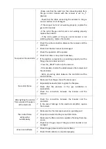
The main burner
automatically turns off
after the fireplace
reaches a certain
temperature
✓
Check the thermostat setting.
✓
Check if draft reductor is mounted properly.
There is sediment
deposited on the glass
✓
Make sure the holes of the main burner are not blocked.
✓
Check that the gas pressure in the installation is correct.
✓
Check that nothing blocks the chimney system.
The device cannot be
turned off using the
remote control
✓
Try turning off the burner using the switch on the gas
control module,
setting it to „O”. If there is no response,
replace the gas control module.
✓
Check the connection between the breaker and the
controller.
RATING PLATE INFORMATION
SAMPLE RATING AND INFORMATION PLATES BELOW. DO NOT REMOVE THE PLATES FROM ITS
ORIGINAL POSITION AS THOSE HAVE TO REMAIN WITH THE APPLIANCE AT ALL TIME.
Kratki.pl
Marek Bal
ul. Gombrowicza 4
26-600 Jedlinsk Wsola
Poland
Tel: +48 48 384 44 88
www.kratki.com
Product Code:
LEO/100/NG
Name:
LEO 100 series vented gas fireplace heater
Type of appliance:
Vented Gas Fireplace Heater
Conforms to:
ANSI 21.88-14
Certified to:
CSA 2.33-14, CSA P.4.1-15, CAN/CGA 2/17-M91
XXXXXXXX
Gas type suitable for the appliance:
Input rate (BTU/hr):
Manifold pressure 0-610m (in. w.c./kPa):
Manifold pressure 610-1370m (in. w.c./kPa):
Manifold pressure, Low setting (in. w.c./kPa):
NG (natural gas)
22000
3,5/0,87
4,8/1,20
0,9/0,22
Содержание LEO/100
Страница 6: ...DIMENSIONS...
Страница 7: ......
Страница 8: ...Figure 1 Leo series dimmensions...
Страница 25: ...VENT TERMINATION HORIZONTAL SIDE WALL VENTING SYSTEM REQUIREMENTS Figure 8 Venting system requirements...
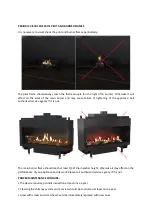
Страница 36: ...PROPER installation of decorative logs...


