background image

KRAMER:  SIMPLE CREATIVE TECHNOLOGY


Controlling the VP-725DSA Presentation Switcher / Scaler 


40 


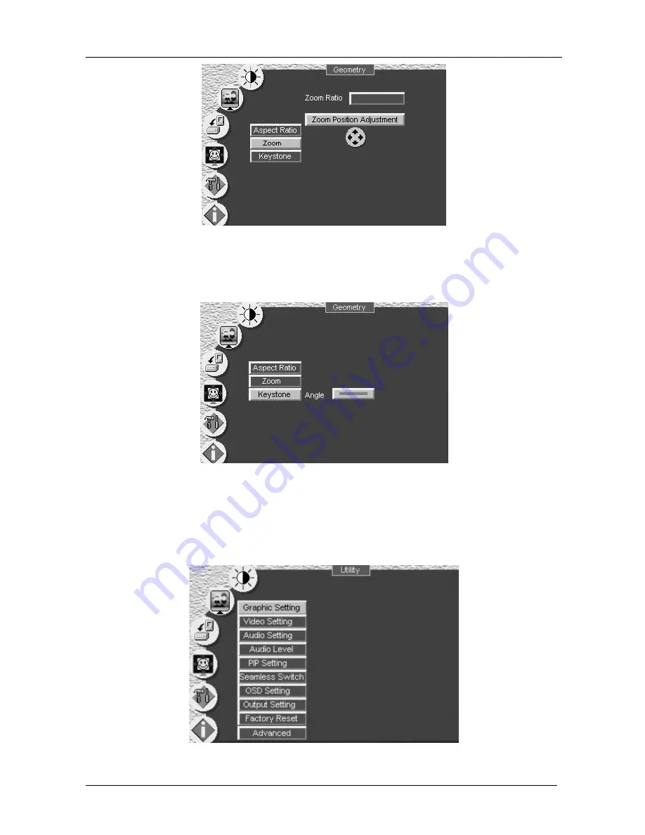
Figure 33: Geometry (Zoom Position Adjustment) Screen 

You can adjust the Keystone (to keep the picture rectangular) according to 

your specific requirements (see Figure 34). 


Figure 34: Geometry (Keystone) Screen 

9.1.5 

Configuring via the Utility Screens 

You can determine how your 

VP-725DSA

 will function either generally or on 

a specific occasion, via the Utility screen settings (see Figure 35): 


Figure 35: Utility Screen 

Содержание VP-725DSA

Страница 1: ...Kramer Electronics Ltd USER MANUAL Model VP 725DSA Presentation Switcher Scaler...

Страница 2: ...Understanding the Video Group Mode Scaler Mode 21 7 2 Understanding the Audio Group Mode Master Audio Group Mode 21 7 3 Understanding the Audio Features 22 7 3 1 Choosing Audio Follow Video or Audio...

Страница 3: ...are 56 9 4 2 Configuring the Ethernet Connection 56 9 4 2 1 The Configuration Screen 56 9 4 3 Control the VP 725DSA via the Ethernet Serial Port 58 10 Using Text Overlay 60 10 1 Downloading the TextOv...

Страница 4: ...gure 38 Choosing the Video Utility Settings 42 Figure 39 Video Setting Standard Utility Screen 42 Figure 40 Choosing the Audio Utility Settings 43 Figure 41 Choosing the Audio Level Settings 44 Figure...

Страница 5: ...the Audio Level Settings 44 Table 14 Choosing the PIP Utility Settings 45 Table 15 Choosing the Seamless Switch Utility Settings 46 Table 16 Choosing the OSD Utility Settings 47 Table 17 Choosing the...

Страница 6: ...dustry Table 2 defines how to connect the wires to the connectors on both ends of the cable When manually connecting the ends of a cable both connectors must follow the same standard either EIA TIA 56...

Страница 7: ...hese items VP 725DSA Presentation Switcher Scaler Power cord2 Infra red remote control transmitter including the required battery Null modem adapter This user manual3 2 Getting Started We recommend th...

Страница 8: ...UT L L G R R L L G R R L L G R R L L G R R L L G R R L L G R R L L G R R L L G R R L L G R R L L G R R L L G R R L L G R R L L G R R L L G R R L L G R R L L G R R L L G R R L L G R R L L G R R AUDIO O...

Страница 9: ...reprocesses the signal to correct mastering errors and regenerates the video at a chosen line and pixel rate format providing for example native resolution video for LCD DLP and Plasma displays Facili...

Страница 10: ...rols via the MENU and LCD status display and OSD when appropriate RS 232 and the infra red remote control transmitter Audio breakaway option to switch audio independently from video or Audio follow vi...

Страница 11: ...From the front panel high contrast LCD Display see section 9 2 Remotely from the infra red remote control transmitter see section 9 3 Via Ethernet see section 9 4 Remotely via RS 232 Achieving the be...

Страница 12: ...PIP ENTER UP DOWN OSD ON 2 2 2 2 2 3 3 3 3 4 4 4 4 VIDEO GROUP AUDIO GROUP MASTER AUDIO SCALER OVERRIDE TALKOVER LINE MIC OUT MIX SELECT MIC CONTROL AUDIO LEVEL VIDEO GROUP AUDIO GROUP MASTER AUDIO SC...

Страница 13: ...TALKOVER 8 Routes the selected input to the output until an audio signal is detected on the microphone input When this happens the selected input is faded out to be faded back in when no input is dete...

Страница 14: ...the selection of an alternative video input for scaling 27 SELECT 1 Buttons MASTER AUDIO When selected routes the selected audio input one of 18 to the MASTER OUT terminal block connector Figure 2 an...

Страница 15: ...60 Hz Mic IN COND MIC DYN MIC AUDIO INPUTS AUDIO OUTPUTS CV 2 CV 3 CV 4 YC 1 YC 2 YC 3 YC 4 VGA 1 VGA 2 VGA YC CV CV 1 ETHERNET VGA 3 VGA 4 COMP 1 COMP 2 COMP 3 COMP 4 DVI 1 DVI 2 MASTER OUT L L G R...

Страница 16: ...deo Y C sources from 1 to 4 16 ETHERNET port Connects to your LAN1 17 CV OUT BNC Connector Connects to the composite video acceptor 18 CV IN BNC Connectors Connects to the composite video sources from...

Страница 17: ...Refer to the appropriate nameplate ratings for information For example for fuse replacement see the value printed on the product label 5 The machine is earthed grounded in a reliable way and is connec...

Страница 18: ...VGA graphics sources for example computers VGA Source 1 VGA Source 2 VGA Source 3 and VGA Source 4 to the HD15 input connectors2 Up to four composite video sources3 CV Source 1 CV Source 2 CV Source...

Страница 19: ...or to the respective video inputs on the projector Connect the MASTER OUT terminal block connector to the balanced audio input on the audio amplifier Select any one of the three audio inputs to route...

Страница 20: ...KRAMER SIMPLE CREATIVE TECHNOLOGY Connecting the VP 725DSA Presentation Switcher Scaler 14 Figure 3 Connecting the VP 725DSA Presentation Switcher Scaler...

Страница 21: ...1 Projector Acceptor Amplifier Figure 4 Connecting the MASTER OUT in Master Audio Mode 6 1 2 Using the MASTER OUT in the Master AV Mode In the Master AV Mode see Figure 5 you can convert the component...

Страница 22: ...dapter provided with the machine recommended Connect the RS 232 DB9 rear panel port on the VP 725DSA unit to the Null modem adapter and connect the Null modem adapter with a 9 wire flat cable to the R...

Страница 23: ...PINOUT Side 1 Side 2 PIN Wire Color PIN Wire Color 1 Orange White 1 Green White 2 Orange 2 Green 3 Green White 3 Orange White 4 Blue 4 Blue 5 Blue White 5 Blue White 6 Green 6 Orange 7 Brown White 7 B...

Страница 24: ...P and click the Properties Button see Figure 8 Figure 8 Local Area Connection Properties Window 5 Select Use the following IP Address1 and fill in the details as shown in Figure 9 Figure 9 Internet Pr...

Страница 25: ...the Ethernet port on a network hub or network router via a straight through cable with RJ 45 connectors as Table 5 defines Table 5 Straight through Cable RJ 45 PINOUT Side 1 Side 2 PIN Wire Color PIN...

Страница 26: ...tereo Audio Input Output Figure 10 Figure 11 and Figure 12 illustrate how to wire a balanced unbalanced input and or output connection L L G R R Figure 10 Connecting a Balanced Stereo Audio Input Outp...

Страница 27: ...t for DVI once a DVI input is selected in the Scaler Mode that DVI input selection cannot be changed in the Video Group Mode In both the Video Group and the Scaler Mode you can adjust2 the Audio Level...

Страница 28: ...r Out 7 3 Understanding the Audio Features This section describes Switching balanced stereo audio signals in audio follow video or breakaway modes see section 7 3 1 Adjusting the audio level see secti...

Страница 29: ...in the button illuminates 7 3 3 Using the Microphone CONTROL Modes Using the MIC CONTROL2 buttons and or the OSD you can do the following Override3 which sends the signal from the microphone to the Ma...

Страница 30: ...1 Activating the PIP Feature To activate the PIP which illuminates the PIP button do one of the following Press the PIP button Switch on the PIP functionality via the OSD Menu Press the PIP key on the...

Страница 31: ...al and Vertical position placing it anywhere on the screen 7 4 3 Toggling between the PIP and the Screen Source SWAP To toggle back and forth between the PIP content and the screen source content do t...

Страница 32: ...e Up and or Down navigation control keys on the infra red remote control transmitter see Figure 55 or the UP and or DOWN front panel OSD buttons Use the OSD Menu 7 4 5 Moving the Position of the PIP T...

Страница 33: ...for a few seconds until the Key Lock On OSD status appears superimposed over the top right corner of the screen when the Source Prompt is ON for a few seconds2 as Figure 15 illustrates Figure 15 Lock...

Страница 34: ...16 OSD Input Status You can also use the INPUT SELECTOR button to freeze the image see section 8 1 1 or to display a blank screen see section 8 1 2 8 1 1 Freezing the Image You can freeze the image by...

Страница 35: ...utton flashes The Freeze OSD status appears superimposed over the top right corner of the screen when the Source Prompt is ON for a few seconds1 2 Press the appropriate flashing INPUT SELECTOR front p...

Страница 36: ...5 or via the Output Setting OSD menu see Table 17 The OSD status appears superimposed over the top right corner of the screen when the Source Prompt is ON for a few seconds1 as Figure 17 illustrates2...

Страница 37: ...the MENU key on the infra red remote control transmitter see Figure 55 displays the first OSD screen the Brightness and Contrast screen see Figure 18 If the OSD is locked1 pressing the MENU front pane...

Страница 38: ...rightness and Contrast Brightness and Contrast Level 1 Range Default Brightness 0 to 128 64 Contrast 0 to 128 64 9 1 2 Controlling the Gamma and Color Figure 20 and Table 7 define the Gamma and Color...

Страница 39: ...lue 0 to 32 16 User 1 2 Yellow 0 to 32 16 Choosing User 1 or User 2 from the Gamma and Color Screen illustrated in Figure 20 displays the Gamma Color Temperature and Color Manager Screen in Figure 21...

Страница 40: ...p Audio Group AV Group Scaler Master Audio Select Master AV VGA1 VGA2 VGA3 VGA Group VGA4 DVI1 DVI Group DVI2 Comp1 Comp2 Comp3 Comp Group Comp4 YC1 YC2 YC3 YC Group YC4 AV1 AV2 AV3 AV Group AV4 VGA1...

Страница 41: ...oup Figure 25 illustrates the Source Figure 25 Selecting the Source 1 Selects the video input from each group CV YC Component VGA DVI for switching to its local group output 2 Selects the audio breaka...

Страница 42: ...angle Figure 26 Geometry Screen Table 9 Controlling the Geometry Geometry Level 1 Level 2 Level 3 Range Default Anamorphic Virtual Wide Letterbox Pan 32 to 32 0 Left Up Right Up Center Left Down Nativ...

Страница 43: ...ttom of the screen native lets you set the native resolution according to the specifications of the plasma screen or projector 4 3 output the length to height ratio is 4 3 and user define H Zoom V Zoo...

Страница 44: ...ondingly and the change is reflected in the pop up OSD Enlarge status box For example Figure 30 illustrates a zoom ratio increase from 200 Image A to 400 Image B Figure 30 Zoom Ratio Adjustment Exampl...

Страница 45: ...atio Screen 9 1 4 2 Adjusting the Zoom Position You can adjust the zoom position see the example in Figure 31 via one or more of the following methods Using the navigation control keys on the infra re...

Страница 46: ...n adjust the Keystone to keep the picture rectangular according to your specific requirements see Figure 34 Figure 34 Geometry Keystone Screen 9 1 5 Configuring via the Utility Screens You can determi...

Страница 47: ...128 V Position 0 to 255 128 Color 0 to 128 70 Hue 0 to 128 64 Sharpness 0 to 16 8 Frequency 0 to 100 49 Phase 0 to 31 0 Auto Image Graphic Setting Auto Gain Selecting the color format see Figure 37 le...

Страница 48: ...g Color Format Utility Screen 9 1 5 2 Choosing the Video Utility Settings Figure 38 and Table 11 define the Video Setting Utility screen You can set the Color Format Standard see Figure 39 color hue s...

Страница 49: ...to 128 64 Sharpness 0 to 16 11 H Position 0 to 20 15 Video Setting V Position 0 to 20 10 9 1 5 3 Choosing the Audio Utility Settings Figure 40 and Table 12 define the Audio Setting Utility screen Fig...

Страница 50: ...osing the Audio Level Settings Utility Level 1 Level 2 Range Default VGA Grp In 0 to 255 160 VGA Grp Out 0 to 255 160 DVI Grp In 0 to 255 160 DVI Grp Out 0 to 255 160 Comp Grp In 0 to 255 160 Comp Grp...

Страница 51: ...ition of the PIP Figure 42 Choosing the PIP Utility Settings Table 14 Choosing the PIP Utility Settings Utility Level 1 Level 2 Level 3 Range Default Off PIP On Off On VGA 1 VGA 2 VGA 3 VGA 4 DVI 1 DV...

Страница 52: ...g the Seamless Switch Utility Settings Table 15 Choosing the Seamless Switch Utility Settings Utility Level 1 Level 2 Default Fast Moderate Seamless Switch Safe Blue Background Black Blue 1 FAST an im...

Страница 53: ...e Figure 46 Figure 44 Choosing the OSD Utility Settings Table 16 Choosing the OSD Utility Settings Utility Level 1 Level 2 Level 3 Range Default H Position 0 to 36 18 V Position 0 to 36 18 Time Out 3...

Страница 54: ...e 17 define the Output Setting Utility screen You can set the resolution1 see Figure 48 refresh rate see Figure 49 color format and a user definable output mode2 see Figure 50 and Table 18 Figure 47 C...

Страница 55: ...852x480 1152x864 1280x1024 1400x1050 1152x870 1600x1200 480P 1152x900 852x1024i 720P 1280x960 1024x1024i 1080i 1280x768 1366x768 576P 1024x576 Resolution 1365x1024 720x400 User Define Refresh Rate 60...

Страница 56: ...active region HP Horizontal polarity VT Vertical total VW Vertical sync pulse width VS Vertical active start point VA Vertical active region VP Vertical polarity OCLK Output clock Confirm Confirm the...

Страница 57: ...ss once to insert blank screen press again to return to display Ignore input button ignores freeze and blank you can freeze the frame or insert a blank screen only via the Freeze and Blank buttons res...

Страница 58: ...her Scaler 52 9 1 6 Verifying Configuration Details via the Information Screen From the Information screen see Figure 53 you can verify information that includes the main source the PIP source the out...

Страница 59: ...CD Display using the front panel buttons do the following 1 Turn the VP 725DSA unit ON and press the OSD ON button if selected 2 Press the appropriate front panel OSD buttons as defined in Figure 54 F...

Страница 60: ...KRAMER SIMPLE CREATIVE TECHNOLOGY Controlling the VP 725DSA Presentation Switcher Scaler 54 Figure 55 Infra red Remote Control Transmitter...

Страница 61: ...ontrast PIP Toggles the picture in picture function and illuminates turns off the PIP button see section 7 1 SWAP Toggles between the PIP content and the screen source content see section 7 4 3 CONTRA...

Страница 62: ...file on your computer 3 Run the installer setup 4 Respond to the installation wizard prompts 5 Restart your system 9 4 2 Configuring the Ethernet Connection Double click the VP725 Ethernet AP exe ico...

Страница 63: ...erver list Delete Press to delete an IP number Add Press to manually add a server Com Port or IP Number Save Press to save Server settings Load Press to load Server settings To search for devices clic...

Страница 64: ...P725 Ethernet Application screen click the Control tab The Control screen appears see Figure 60 The Control tab includes a set of control buttons which enable you to operate and control the machine vi...

Страница 65: ...P MUTE and KEYLOCK buttons which appear only on the remote control transmitter A Connection Status area consisting of a connection indicator and the device IP number A Message area recording all the o...

Страница 66: ...the screen with a rich feature set including text color and speed transparency text position and repetition Current text overlay settings can be saved and loaded to the AP Before running this program...

Страница 67: ...thernet2 RS 232 Check box When selected set the COM port and Baud Rate 9600 for VP 725DSA to connect via the RS 232 connector 2 VP725 Check box Select VP725 when connected to a VP 725 series machine C...

Страница 68: ...extOverlay Program To use the TextOverlay Application download the Text Overlay software from our Web site1 and follow the on screen instructions 10 2 Setting the Text Message The text overlay paramet...

Страница 69: ...necting and Disconnecting the TextOverlay Program To connect the TextOverlay program do the following 1 Open the TextOverlay program The TextOverlay application screen appears4 2 Select the VP 725 che...

Страница 70: ...t Overlay button 7 Click the Send button in the Send Text area Text starts running over the display If you need to change any of the settings while the text message is running do so according to secti...

Страница 71: ...HD15F connector 1 x RGBHV YPbPr on BNC connectors 1 x DVI D on a DVI I connector Master Audio Output MASTER AUDIO OUTPUT 1 x balanced stereo audio on terminal block connector 22dBm OUTPUT RESOLUTIONS...

Страница 72: ...32 CR DoneCR command setting success 2 Y 10 5 CR get current output resolution Z 10 5 2 CR current resolution is 1024x768 3 Y 0 35 CR Keypad Remote controller set Menu ON OFF Z 0 35 CR DoneCR command...

Страница 73: ...VP 725DSA only 0 29 N A Audio Level VP 725DSA only 0 30 N A Audio Level Line VP 725DSA only 0 31 N A Audio Level Mic VP 725DSA only 0 32 N A Audio Level Out VP 725DSA only 0 33 N A Auto Image 0 34 N A...

Страница 74: ...2 Get 21 0 255 Audio Setting Treble Level VP 725DSA only 1 Set 2 Get 22 0 255 Audio Setting Bass Level VP 725DSA only 1 Set 2 Get 23 0 255 Audio Setting Balance Level VP 725DSA only 1 Set 2 Get 24 0...

Страница 75: ...Input Level VP 725DSA only 1 Set 2 Get 49 0 255 Audio Level DVI2 Input Level VP 725DSA only 1 Set 2 Get 50 0 255 Audio Level COMP1 Input Level VP 725DSA only 1 Set 2 Get 51 0 255 Audio Level COMP2 Inp...

Страница 76: ...1 Set 2 Get 76 0 32 Gamma and Color User2Color Manager Blue 1 Set 2 Get 77 0 32 Gamma and Color User2 Color Manager Yellow Control Type Function Param for Set Function Description Comment 3 Set 4 Get...

Страница 77: ...A1 1 VGA2 2 VGA3 3 VGA4 4 DVI1 5 DVI2 6 COMP1 7 COMP2 8 COMP3 9 COMP4 10 YC1 11 YC2 12 YC3 13 YC4 14 AV1 15 AV2 16 AV3 17 AV4 3 Set 4 Get 16 0 4 PIP Setting PIP Size 0 1 25 1 1 16 2 1 9 3 1 4 4 Split...

Страница 78: ...nk 0 Off 1 On 9 Set 10 Get 4 0 1 Key Lock 0 Off 1 On 9 Set 10 Get 5 0 26 Output Resolution 0 640x480 1 800x600 2 1024x768 3 1280x1024 4 1600x1200 5 852x1024i 6 1024x1024i 7 1366x768 8 1365x1024 9 1280...

Страница 79: ...1 Partial Transparency 2 Normal 8 Background RGB Color T1AE5 R G B RGB color 0 255 9 Background Partial Transparency Color T1BE4 R G B RGB color 0 255 10 TextOverlay On T1CE3 NA NA NA Enable TextOverl...

Страница 80: ...is required the original dated invoice or a copy must be presented as proof of warranty coverage and should be included in any shipment of the product Please also include in any mailing a contact name...

Страница 81: ...or the latest information on our products and a list of Kramer distributors visit our Web site www kramerelectronics com where updates to this user manual may be found We welcome your questions commen...

Отзывы: