COMe-bSL6 – User Guide Rev. 1.4
www.kontron.com
// 50
5/
Interface Connectors X1A and X1B
The COMe-bSL6 is a COM Express® basic module containing two 220-pin connectors; each with two rows called row
A & B on primary connector and row C & D on secondary connector.
The following figure is a view of the bottom of the module showing the position of interface connectors X1A and X1B.
Figure 4: X1A and X1B COMe Interface Connectors
5.1.
X1A and X1B Signals
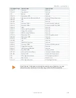
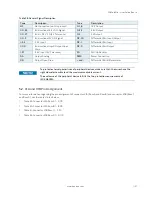
For a description of the terms used in the X1A and X1B pin assignment tables, see Table 28: General Signals
Description table or Appendix A, List of Acronyms. If a more detailed pin assignment description is required, refer to
the PICMG specification COMe Rev 2.1 Type 6 standard.
The information provided under type, module terminations and comments is complimentary
to the COM.0 Rev 2.1 Type 6 standard. For more information, contact Kontron Support.
X1B
X1A


