COMe-bSL6 – User Guide Rev. 1.4
www.kontron.com
// 76
Sub-Screen
Function
Second level Sub-Screen / Description
SIO
Configuration>
(continued)
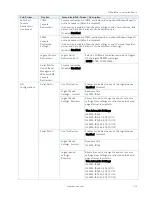
Additional Information SIO:
If they exist, additional interfaces such as Serial Port 2, Serial Port 3 and Parallel Port will be
included within the SIO Configuration setup page.
The SIO Configuration menu enables all available serial interfaces to be configured. The
module-based serial interfaces always appear as COM1 and COM2. COM 1 and COM 2 can be
treated as 16550-compatible legacy COM interfaces at the standard I/O addresses and are
based in the on-module CPLD. Note: Hardware flow control is not supported.
Optionally, If the baseboard contains an activated SuperIO of the type Winbond 83627, then its
serial interfaces are added to the system as COM3 and COM4. COM3 and COM4 IRQ and I/O
addresses are configurable in this menu, too.
Although the chipset internal COMs are not supported due to technical constraints their driver
must be installed. Installing the driver does not mean that these serial interfaces are useable.
Warning: Logical Devices state on the left side of the control reflects the current logical device
state. Changes made during the setup session are shown after restarting the system.
PCI Subsystem
Settings>
PCI Latency
Timer>
Displays value to be programmed into the PCI latency timer register
[32, 64, 96, 128, 160, 192, 224, 248]
PCI-X Latency
Timer>
Displays value to be programmed into the PCI latency timer register
[32, 64, 96, 128, 160, 192, 224, 248]
VGA Palette
Snoop>
Enables or disables VGA palette register snooping
[Enabled, Disabled]
PERR#
Generation>
Enables or disables PCI device to generate PERR#
[Enabled, Disabled]
SERR#
Generation>
Enables or disables PCI device to generate SERR#
[Enabled, Disabled]
Above 4G
Decoding>
Enables or disables decoding in Address Space above ‘4G’ for 64 bit
capable devices. Note: Only if system supports 64 bit PCI decoding.
[Enabled, Disabled]
PCI Hot-Plug
Settings>
BIOS
Hot Plug
Support>
Enable – allows BIOS built in hot-plug support
Note: Use if OS does not support PCIe and SHPC hot-plug
natively.
[Enabled, Disabled]
PCI Buses
Padding>
Padd PCI Buses behind the bridge for hot-plug
[Disabled, 1, 2, 3, 4, 5]
I/O Resources
Padding>
Padd PCI resources behind the bridge for hot-plug
[Disabled, 4 k, 8 k, 16 k, 32 k]
MMIO 32 bit
Resources
Padding>
Padd PCI MMIO 32 bit resources behind the bridge for
hot-plug.
[Disabled, 1 M, 2 M, 4 M, 8 M, 16, M, 32 M, 64 M, 128 M]
PFMMIO 32 bit
Resources
Padding>
Padd PCI MMIO 32 bit pre-fetchable resources behind
the bridge for hot-plug.
[Disabled, 1 M, 2 M, 4 M, 8 M, 16, M, 32 M, 64 M, 128 M]
Network Stack
Configuration>
Network Stack>
If UEFI network stack is enabled, the Ethernet chip is active.
[Enabled, Disabled]
CSM
Configuration>
CSM Support>
Enables or disables CSM Support
If enabled, the CSM details can be changed. Below ‘Option ROM Execution’
are ‘Network, ‘Storage’, ’Video’ and ‘Other PCI devices’.


