COMe-bSL6 – User Guide Rev. 1.4
www.kontron.com
// 61
5.2.4.
Connector X1B Row D
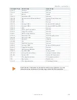
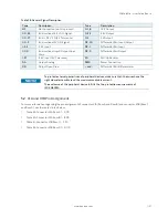
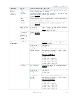
The following table lists the pins for connector X1B row D.
Table 32: Connector X1B Row D Pinout List
Pin
COME Signal
Description
Type
Termination
Comment
D1
GND
Power Ground
PWR GND
D2
GND
D3
USB_SSTX0-
Additional transmit signal for SuperSpeed
USB data path 0
DP-O
D4
US
D5
GND
Power Ground
PWR GND
D6
USB_SSTX1-
Additional transmit signal for SuperSpeed
USB data path 1
DP-O
D7
US
D8
GND
Power Ground
PWR GND
D9
USB_SSTX2-
Additional transmit signal for SuperSpeed
USB data path 2
DP-O
D10
US
D11
GND
Power Ground
PWR GND
D12
USB_SSTX3-
Additional transmit signal for SuperSpeed
USB data path 3
DP-O
D13
US
D14
GND
Power Ground
PWR GND
D15
DDI1_CTRL
DDI1 Clock
I/O-3.3
PD 100 k
Ω
D16
DDI1_CTRLDATA_AUX-
DDI1 Date
I/O-3.3
PU 100 k
Ω,
3.3 V
(S0)
D17
RSVD
Reserved for future use
NC
D18
RSVD
D19
P
PCI Express transmit lane pair 6
DP-O
D20
PCIE_TX6-
D21
GND
Power Ground
PWR GND
D22
P
PCI Express transmit lane pair 7
DP-O
D23
PCIE_TX7-
D24
RSVD
Reserved for future use
NC
D25
RSVD
D26
DDI
DDI1 pair 0
DP-O
D27
DDI1_PAIR0-
D28
RSVD
Reserved for future use
NC
D29
DDI
DDI1 pair 1
DP-O
D30
DDI1_PAIR1-
D31
GND
Power Ground
PWR GND
D32
DDI
DDI1 pair 2
DP-O
D33
DDI1_PAIR2-
D34
DDI1_DDC_AUX_SEL
DDI1 select
I-3.3
PD 1 M
Ω
D35
RSVD
Reserved for future use
NC
D36
DDI
DDI1 pair 3
DP-O
D37
DDI1_PAIR3-
D38
RSVD
Reserved for future use
NC
D39
DDI
DDI2 pair 0
DP-O
D40
DDI2_PAIR0-
D41
GND
Power Ground
PWR GND
D42
DDI
DDI2 pair 1
DP-0
D43
DDI2_PAIR1-
D44
DDI2_HPD
DDI2 Hotplug Detect
I-3.3
PD 100 k
Ω
D45
RSVD
Reserved for future use
NC


