COMe-bSL6 – User Guide Rev. 1.4
www.kontron.com
// 53
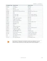
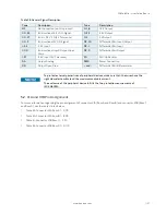
Pin
COME Signal
Description
Type
Termination
Comment
A38
USB_6_7_OC#
USB overcurrent indicator port 6/7
I-3.3
PU 10 k
Ω,
3.3 V
(S5)
A39
USB4-
USB 2.0 data differential pair port 4
DP-I/O
PD 14.25 k
Ω
to
24.8 k
Ω
in PCH
A40
USB4+
A41
GND
Power Ground
PWR GND
A42
USB2-
USB 2.0 data differential pair port 2
DP-I/O
PD 14.25 k
Ω
to
24.8 k
Ω
in PCH
A43
USB2+
A44
USB_2_3_OC#
USB overcurrent indicator port 2/3
I-3.3
PU 10 k
Ω
3.3 V
(S5)
An open drain driver from
a USB current monitor on
the Carrier Board may
drive this line low. Do not
pull this line high on the
Carrier Board
A45
USB0-
USB 2.0 data differential pairs port 0
DP-I/O
PD 14.25 k
Ω
to
24.8 k
Ω
in PCH
A46
USB0+
A47
VCC_RTC
Real Time Clock (RTC) circuit power input
PWR 3V
Voltage range 2.8 V to
3.47 V
A48
EXCD0_PERST#
ExpressCard reset port 0
O-3.3
PD 10 k
Ω
A49
EXCD0_CPPE#
ExpressCard capable card request port 0
I-3.3
PU 10 k
Ω
3.3 V
(S0)
A50
LPC_SERIRQ
Serial interrupt request
I/OD-3.3
PU 8.2 k
Ω,
3.3 V
(S0)
A51
GND
Power Ground
PWR GND
A52
P
PCI Express transmit lane 5
DP-O
A53
PCIE_TX5-
A54
GPI0
General purpose input 0
I-3.3
PU 100 k
Ω
, 3.3 V
(S0)
A55
P
PCI Express transmit lane 4
DP-O
A56
PCIE_TX4-
A57
GND
Power Ground
PWR GND
A58
P
PCI Express transmit lane 3
DP-O
A59
PCIE_TX3-
A60
GND
Power Ground
PWR GND
A61
P
PCI Express transmit lane 2
DP-O
A62
PCIE_TX2-
A63
GPI1
General purpose input 1
I-3.3
PU 100 k
Ω
, 3.3 V
(S0)
A64
P
PCI Express transmit lane 1
DP-O
A65
PCIE_TX1-
A66
GND
Power Ground
PWR GND
A67
GPI2
General purpose input 2
I-3.3
PU 100 k
Ω
, 3.3 V
(S0)
A68
P
PCI Express transmit lane 0
DP-O
A69
PCIE_TX0-
A70
GND
Power Ground
PWR GND
A71
LVDS channel A DAT0 or EDP Lane 2 transmit
DP-O
A72
LVDS_A0-
A73
LVDS channel A DAT1 or EDP Lane 1 transmit
DP-O
A74
LVDS_A1-
A75
LVDS channel A DAT2 or EDP Lane 0 transmit
DP-O
A76
LVDS_A2-
A77
LVDS_VDD_EN
LVDS or EDP panel power control
O-3.3
PD 100 k
Ω
A78
LVDS channel A DAT3
DP-O
A79
LVDS_A3-


