


UPS306-01-00 PowerWAVE 9000 DPA User Manual Dated 01-06-2010
4-9
4: Operation
4.5
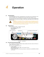
Operating Instructions
Under normal operating conditions all the UPS modules in a multi-module system are running, and operating
in the ‘On Line’ (On Inverter) mode.
The following procedures are provided in this section:
How to transfer the load to the Maintenance Bypass and shut down the UPS system for maintenance
purposes –
(See paragraph 4.5.1)
.
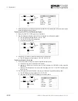
How to start up the UPS system and transfer the load from the Maintenance Bypass to the inverters (‘On
Line’ mode)
(See paragraph 4.5.2)
.
How to shut down the entire UPS system
(See paragraph 4.5.3)
.
How to stop/start one module in a redundant multi-module system
(See paragraph 4.5.4)
.
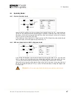
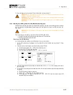
4.5.1 Transfer to Maintenance Bypass Mode
If needed, to perform service or maintenance, it is possible to transfer the load to Maintenance Bypass Mode
and power down the UPS module(s) whilst leaving the load connected to the raw bypass mains supply.
This procedure describes the sequence of operations to transfer the load to the Maintenance Bypass supply
and then shut down, and isolate, the UPS Module(s).
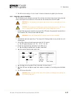
Prior to commencing this procedure, check and confirm the following UPS system status (on all modules in a
parallel system):
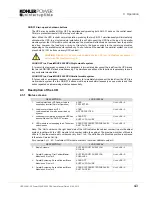
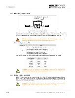
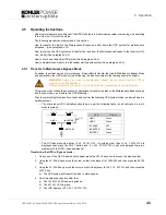
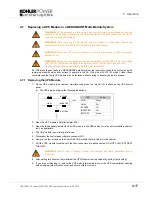
• The mimic panel LED indications should be as per the following table (on all cabinets in a multi-
module system):
• The LCD panel should display
LOAD PROTECTED
. If anything other than
LOAD PROTECTED
is
displayed then press the
RESET
button, and if
LOAD PROTECTED
is still not displayed there is a
problem with the UPS – seek assistance!
Transferring the UPS to ‘Bypass’ mode:
1.
On any one of the UPS module’s mimic panel press the
ENTER
key once to access the menu system.
2.
Using the
UP/DOWN
keys, move the cursor so that it is adjacent to
COMMANDS
and then press the
ENTER
key.
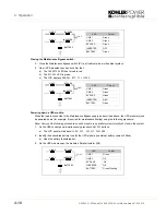
3.
Using the
UP/DOWN
keys, move the cursor so that it is adjacent to
LOAD TO BYPASS
and then press the
ENTER
key.
a)
The UPS system will transfer the load to static bypass.
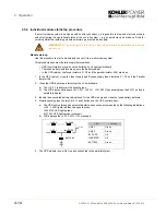
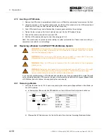
4.
On all modules
check and confirm that:
a)
The
INVERTER
LED has extinguished.
b)
The
BYPASS
LED is green.
c)
The LCD displays
LOAD NOT PROTECTED
.
WARNING:
Before you close the Maintenance Bypass isolator ensure that the UPS is
operating in the Bypass Mode.
All the operations in this section must be performed by authorised and trained personnel.
LED
Colour
LINE 1
Green
LINE 2
Green
BY PASS
OFF
INVERTER
Green
BATTERY
Green
LINE 1
LINE 2
BY PASS
INVERTER
BATTERY
LOAD
Содержание PW 9000DPA
Страница 1: ...User Manual Pioneering solutions for total power protection Kohler PW 9000DPA ...
Страница 2: ......
Страница 8: ...iv UPS306 01 00 PowerWAVE 9000 DPA User Manual Dated 01 06 2010 ...
Страница 10: ...1 Safety 1 2 UPS306 01 00 PowerWAVE 9000 DPA User Manual Dated 01 06 2010 ...
Страница 18: ...2 Description 2 8 UPS306 01 00 PowerWAVE 9000 DPA User Manual Dated 01 06 2010 ...
Страница 76: ...7 Options 7 6 UPS306 01 00 PowerWAVE 9000 DPA User Manual Dated 01 06 2010 ...
Страница 85: ...UPS306 01 00 PowerWAVE 9000 DPA User Manual Dated 01 06 2010 8 9 8 Specifications ...
Страница 86: ...8 Specifications 8 10 UPS306 01 00 PowerWAVE 9000 DPA User Manual Dated 01 06 2010 ...


