


4: Operation
4-8
UPS306-01-00 PowerWAVE 9000 DPA User Manual Dated 01-06-2010
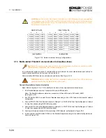
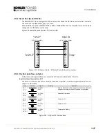
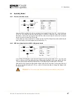
4.4.3 Maintenance Bypass mode
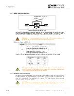
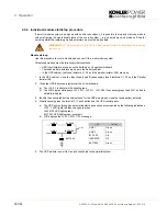
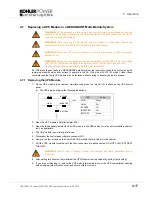
Figure 4.2 Maintenance Bypass Mode
Each module is fitted with a Maintenance Bypass switch (IA1) which, when closed, connects the UPS module
output terminals directly to the UPS Bypass Mains supply. This facility enables a UPS module to be shut
down for maintenance or repair whilst maintaining the load on the raw (unprotected) bypass supply.
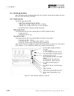
Maintenance Bypass switch (IA1)
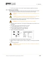
When the UPS is operating on Maintenance bypass the module mimic indications will be as follows
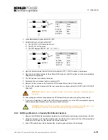
4.4.4 Parallel Isolator switch(IA2)
Each UPS module is provided with an output isolator (IA2). When this isolator is opened it totally disconnects
the UPS module from the output load bus. In a parallel module system this isolates the UPS modules and
allows it to be replaced without having to disturbe the remainder of the system (provided the loss of modules
does not exceed the system redundancy).
WARNING:
In a multi-module system ensure that ALL the UPS modules are operating in the
Bypass mode before transferring the load to Maintenance Bypass (IA1)
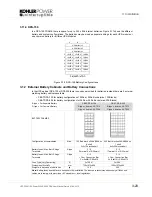
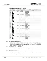
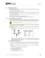
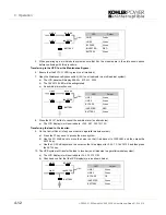
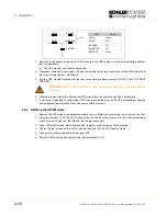
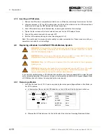
Switch IA1
Effect
ON
Maintenance Bypass-Switch Closed (Load on bypass mains)
LCD-indication:
MAINTENANCE BYP CLOSED
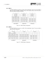
LED Indicators will indicate as shown in table below
OFF
Bypass-Switch Open – Normal operating condition (Load on inverter)
LCD-indication
MAINTENANCE BYP OPEN
LED Indicators will indicate as shown in table below.
LED Indicator
ON
OFF
LINE 1
Green
Green
LINE 2
Green
Green
BYPASS
Green
OFF
INVERTER
RED
ON
BATTERY
Green
Green
CAUTION: If the UPS is operating in the Maintenance Bypass mode the load will not be
protected in the event of a mains failure. It is therefore strongly recommended to switch over to
the On-line mode or Bypass mode as soon as possible.
CAUTION: In a single module configuration the load must be transferred to the maintenance
bypass before the isolator is opened otherwise it will cause a loss of supply.
MAINS
LOAD
MAINTENANCE
BYPASS
UPS
Switch IA1
Содержание PW 9000DPA
Страница 1: ...User Manual Pioneering solutions for total power protection Kohler PW 9000DPA ...
Страница 2: ......
Страница 8: ...iv UPS306 01 00 PowerWAVE 9000 DPA User Manual Dated 01 06 2010 ...
Страница 10: ...1 Safety 1 2 UPS306 01 00 PowerWAVE 9000 DPA User Manual Dated 01 06 2010 ...
Страница 18: ...2 Description 2 8 UPS306 01 00 PowerWAVE 9000 DPA User Manual Dated 01 06 2010 ...
Страница 76: ...7 Options 7 6 UPS306 01 00 PowerWAVE 9000 DPA User Manual Dated 01 06 2010 ...
Страница 85: ...UPS306 01 00 PowerWAVE 9000 DPA User Manual Dated 01 06 2010 8 9 8 Specifications ...
Страница 86: ...8 Specifications 8 10 UPS306 01 00 PowerWAVE 9000 DPA User Manual Dated 01 06 2010 ...


