


2: Description
2-2
UPS306-01-00 PowerWAVE 9000 DPA User Manual Dated 01-06-2010
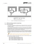
2.3.2 Single/Multi cabinet configurations
Single cabinet system
A single-cabinet system comprises a stand-alone cabinet containing one or more UPS power module(s)
operating as a single-module or module-module system (as defined in paragraph 2.3.1).
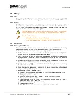
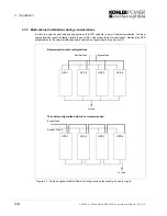
Multi-cabinet system
To further increase the overall system capacity it is possible to connect up to 10 standard cabinets in parallel.
Depending on the model type, each cabinet can contain up to 5 UPS power modules, thereby potentially
resulting in a system comprising up to 50 parallel modules if 10x UPGRADE DPA-125 or 10x UPGRADE
DPA-250 cabinets are employed. Although, in practice, a typical multi-cabinet system will be made up of
fewer than 10 cabinets.
Every standard PowerWAVE 9000 DPA cabinet is provided with the parallel option, eliminating any need for
time-consuming or expensive upgrading on site.
Figure 2.1 PowerWAVE 9000 DPA UPS Multi-Cabinet Chain.
The multi-cabinet configuration is based on a Decentralised Bypass Architecture (DPA) – i.e. every UPS is
provided with its own static bypass. In a parallel system there is always one
master
module and the other
modules are
slaves
. If at any time the master goes faulty the next UPS (former slave) will immediately take
over the master function and the former master will switch off.
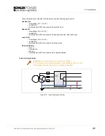
2.3.3 ‘Redundant-module’ versus ‘Capacity’ system
The difference between a ‘
redundant-module
’ system and a ‘
capacity
’ system is that a ‘capacity’ system is
rated such that ALL the UPS power modules are required to provide the necessary output load power. This is
not the case for a ‘redundant-module’ system, whereby the overall system is designed with one (or more)
modules over and above that required to supply the full load. In a redundant-module system it is therefore
possible to lose one (or more) UPS module without affecting the load supply.
Every UPS power module in a parallel configuration is provided with an output parallel Isolator (IA2) which,
when opened, isolates the corresponding module from the parallel system and the module no longer
contributes to the system’s power output. In a ‘capacity’ system opening this isolator this will cause the load
to transfer to the (unprotected) bypass supply. but in a ‘redundant-module’ system the load will continue to
receive protected power until the number of off-line modules exceeds the inbuilt system redundancy.
P o w e rWA V E D P A
E
N
T
E
R
O
N
/
O
F
F
O
N
/
O
F
F
R
E
S
E
T
A
L
A
R
M
L
I
N
E
2
B
Y
P
A
S
S
L
I
N
E
1
I
N
V
E
R
T
E
R
B
A
T
T
E
R
Y
P o w e rWA V E D P A
E
N
T
E
R
O
N
/
O
F
F
O
N
/
O
F
F
R
E
S
E
T
A
L
A
R
M
L
I
N
E
2
B
Y
P
A
S
S
L
I
N
E
1
I
N
V
E
R
T
E
R
B
A
T
T
E
R
Y
P o w e rWA V E D P A
E
N
T
E
R
O
N
/
O
F
F
O
N
/
O
F
F
R
E
S
E
T
A
L
A
R
M
L
I
N
E
2
B
Y
P
A
S
S
L
I
N
E
1
I
N
V
E
R
T
E
R
B
A
T
T
E
R
Y
P o w e rWA V E D P A
E
N
T
E
R
O
N
/
O
F
F
O
N
/
O
F
F
R
E
S
E
T
A
L
A
R
M
L
I
N
E
2
B
Y
P
A
S
S
L
I
N
E
1
I
N
V
E
R
T
E
R
B
A
T
T
E
R
Y
P o w e rWA V E D P A
E
N
T
E
R
O
N
/
O
F
F
O
N
/
O
F
F
R
E
S
E
T
A
L
A
R
M
L
I
N
E
2
B
Y
P
A
S
S
L
I
N
E
1
I
N
V
E
R
T
E
R
B
A
T
T
E
R
Y
P o w e rWA V E D P A
E
N
T
E
R
O
N
/
O
F
F
O
N
/
O
F
F
R
E
S
E
T
A
L
A
R
M
L
I
N
E
2
B
Y
P
A
S
S
L
I
N
E
1
I
N
V
E
R
T
E
R
B
A
T
T
E
R
Y
P o w e rWA V E D P A
E
N
T
E
R
O
N
/
O
F
F
O
N
/
O
F
F
R
E
S
E
T
A
L
A
R
M
L
I
N
E
2
B
Y
P
A
S
S
L
I
N
E
1
I
N
V
E
R
T
E
R
B
A
T
T
E
R
Y
P o w e rWA V E D P A
E
N
T
E
R
O
N
/
O
F
F
O
N
/
O
F
F
R
E
S
E
T
A
L
A
R
M
L
I
N
E
2
B
Y
P
A
S
S
L
I
N
E
1
I
N
V
E
R
T
E
R
B
A
T
T
E
R
Y
P o w e rWA V E D P A
E
N
T
E
R
O
N
/
O
F
F
O
N
/
O
F
F
R
E
S
E
T
A
L
A
R
M
L
I
N
E
2
B
Y
P
A
S
S
L
I
N
E
1
I
N
V
E
R
T
E
R
B
A
T
T
E
R
Y
P o w e rWA V E D P A
E
N
T
E
R
O
N
/
O
F
F
O
N
/
O
F
F
R
E
S
E
T
A
L
A
R
M
L
I
N
E
2
B
Y
P
A
S
S
L
I
N
E
1
I
N
V
E
R
T
E
R
B
A
T
T
E
R
Y
P o w e rWA V E D P A
E
N
T
E
R
O
N
/
O
F
F
O
N
/
O
F
F
R
E
S
E
T
A
L
A
R
M
L
I
N
E
2
B
Y
P
A
S
S
L
I
N
E
1
I
N
V
E
R
T
E
R
B
A
T
T
E
R
Y
P o w e rWA V E D P A
E
N
T
E
R
O
N
/
O
F
F
O
N
/
O
F
F
R
E
S
E
T
A
L
A
R
M
L
I
N
E
2
B
Y
P
A
S
S
L
I
N
E
1
I
N
V
E
R
T
E
R
B
A
T
T
E
R
Y
P o w e rWA V E D P A
E
N
T
E
R
O
N
/
O
F
F
O
N
/
O
F
F
R
E
S
E
T
A
L
A
R
M
L
I
N
E
2
B
Y
P
A
S
S
L
I
N
E
1
I
N
V
E
R
T
E
R
B
A
T
T
E
R
Y
P o w e rWA V E D P A
E
N
T
E
R
O
N
/
O
F
F
O
N
/
O
F
F
R
E
S
E
T
A
L
A
R
M
L
I
N
E
2
B
Y
P
A
S
S
L
I
N
E
1
I
N
V
E
R
T
E
R
B
A
T
T
E
R
Y
P o w e rWA V E D P A
E
N
T
E
R
O
N
/
O
F
F
O
N
/
O
F
F
R
E
S
E
T
A
L
A
R
M
L
I
N
E
2
B
Y
P
A
S
S
L
I
N
E
1
I
N
V
E
R
T
E
R
B
A
T
T
E
R
Y
UPS 1
UPS 2
UPS n
Содержание PW 9000DPA
Страница 1: ...User Manual Pioneering solutions for total power protection Kohler PW 9000DPA ...
Страница 2: ......
Страница 8: ...iv UPS306 01 00 PowerWAVE 9000 DPA User Manual Dated 01 06 2010 ...
Страница 10: ...1 Safety 1 2 UPS306 01 00 PowerWAVE 9000 DPA User Manual Dated 01 06 2010 ...
Страница 18: ...2 Description 2 8 UPS306 01 00 PowerWAVE 9000 DPA User Manual Dated 01 06 2010 ...
Страница 76: ...7 Options 7 6 UPS306 01 00 PowerWAVE 9000 DPA User Manual Dated 01 06 2010 ...
Страница 85: ...UPS306 01 00 PowerWAVE 9000 DPA User Manual Dated 01 06 2010 8 9 8 Specifications ...
Страница 86: ...8 Specifications 8 10 UPS306 01 00 PowerWAVE 9000 DPA User Manual Dated 01 06 2010 ...


