


3: Installation
3-26
UPS306-01-00 PowerWAVE 9000 DPA User Manual Dated 01-06-2010
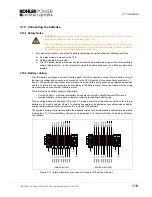
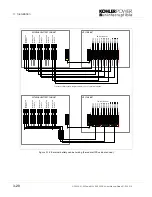
3.14 Interfacing Facilities
Each UPS cabinet contains an Interface Board which has a number of communications interface connectors
that can be uses with a range of I/O options.
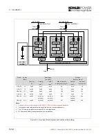
3.14.1 Interface Board
The Interface board has two LEDs:
• Green LED showing the status of the Interface:
- Blinking: 2/sec = Interface is Master (1st Cab. of a System)
- Blinking: 1/sec = Interface is Slave (2nd.. nth cab. of a System)
• Red LED Board Alarm (indicates a possible faulty board)
Master Interface Board
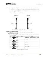
The following ports are active on the Interface Board when fitted to the Master cabinet:
• The Input ports (X1)
• The Output port (X2, X3, X4)
Slave Interface Boards
The following ports are active on the Interface Board when fitted to a Slave cabinet:
• The Output ports X3/6 … X3/10
• The Output ports X4/1 …X4/10 (Means Alarm. Module 1, 2, 3,4, 5)
• All other input or output ports on the Slave boards are not activated
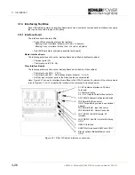
Note:
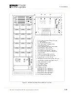
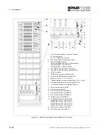
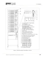
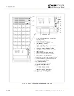
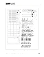
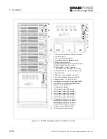
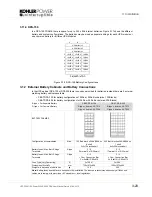
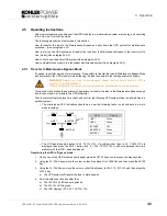
Figure 3.21 shows the interface Board fitted to the DPA-75 cabinet. For details of the other cabinets
refer to Figures 3.7 to 3.12 to identify the location of the components mentioned below.
Figure 3.21 DPA-75 Cabinet interface connections
1.
X1-X4 Customer interface on Phoenix
Terminals:
X1 Customer Inputs
X2…X4 = Outputs Potential free contacts
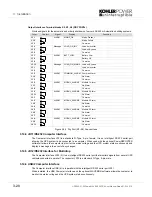
2.
SW1-9 Multi-Cabinet Configuration Switch
3.
JD8 Parallel BUS connector
ONLY For paralleling cabinets use optional
adapter:
JD5 Parallel BUS - Input Connector
JD6 Parallel BUS - Output Connector
4.
JD11 RS232 / Sub D9/ female, PC
interface
5.
JD12 RS232/ Sub D9 / male for Multidrop
ONLY
6.
USB PC Interface
7.
SNMP Slot for optional SNMP card ONLY
8.
Slot for optional Modem/Ethernet card
ONLY
Содержание PW 9000DPA
Страница 1: ...User Manual Pioneering solutions for total power protection Kohler PW 9000DPA ...
Страница 2: ......
Страница 8: ...iv UPS306 01 00 PowerWAVE 9000 DPA User Manual Dated 01 06 2010 ...
Страница 10: ...1 Safety 1 2 UPS306 01 00 PowerWAVE 9000 DPA User Manual Dated 01 06 2010 ...
Страница 18: ...2 Description 2 8 UPS306 01 00 PowerWAVE 9000 DPA User Manual Dated 01 06 2010 ...
Страница 76: ...7 Options 7 6 UPS306 01 00 PowerWAVE 9000 DPA User Manual Dated 01 06 2010 ...
Страница 85: ...UPS306 01 00 PowerWAVE 9000 DPA User Manual Dated 01 06 2010 8 9 8 Specifications ...
Страница 86: ...8 Specifications 8 10 UPS306 01 00 PowerWAVE 9000 DPA User Manual Dated 01 06 2010 ...


