


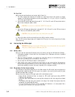
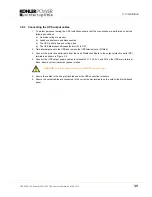

3: Installation
3-10
UPS306-01-00 PowerWAVE 9000 DPA User Manual Dated 01-06-2010
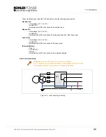
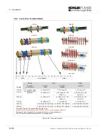
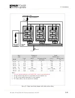
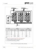
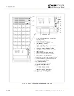
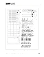
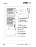
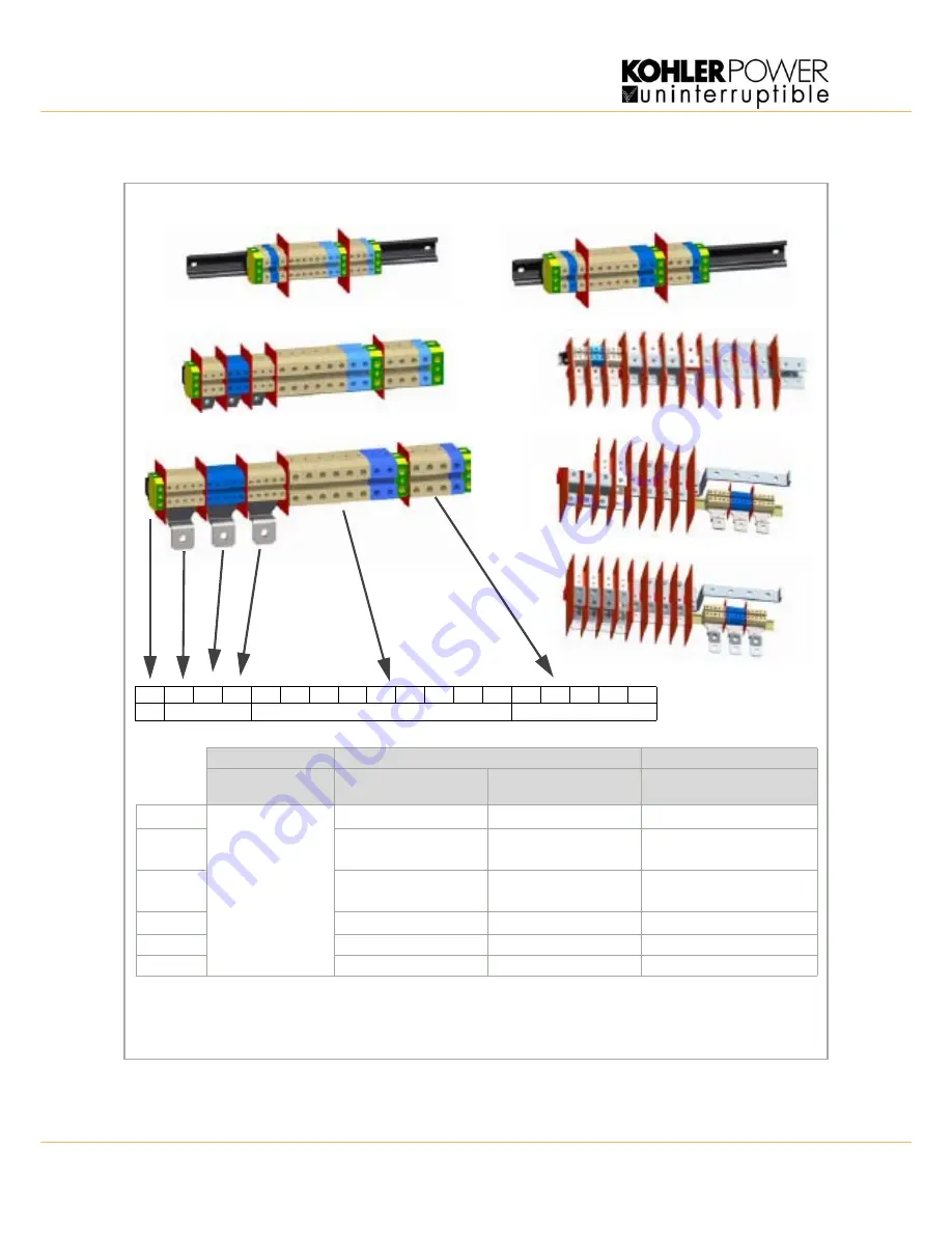
3.9.4 Connection Terminal Details
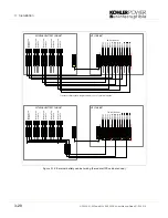
Figure 3.4 Terminal Layouts
FRAME
Battery
Input*
Output*
Separate
(+ / N / -) +PE
Bypass
3+N
Rectifier
3+N+PE
3+N+PE
DPA-25
DC Fuses and cables
are bespoke to the
installation.
4 x 10/16mm
2
(T) 5
x
10/16mm
2
(T)
5 x 10/16mm
2
(T)
DPA-75
4 x 35/50mm
2
(T)
4 x 35/50mm
2
(T) +PE
50mm
2
(T)
4 x 35/50mm
2
(T) +PE
50mm
2
(T)
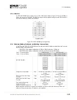
DPA-125
4 x 70/95mm
2
(T)
4 x 70/95mm
2
(T) + PE
50mm
2
(T)
4 x 70/95mm
2
(T) + PE
50mm
2
(T)
DPA-50
4 x 16/25mm
2
(T) 5
x
16/25mm
2
(T)
5 x 16/25mm
2
(T)
DPA-150
3 x M10(B) +PE 1xM10 (B) 4 x M10 (B) +PE 1xM10 (B)
4 x M10 (B) +PE 1xM10 (B)
DPA-250
3 x M12 (B) +PE 1xM12 (B) 4 x M12 (B) +PE 1xM12 (B)
4 x M12 (B) +PE 1xM12 (B)
(T) signifies Terminals. (B) signifies Bar
(See Figure 3.4)
Fuse
and Cable recommendations to IEC 60950-1:2001 or locally recoginsed standards.
The fuse and cable rating details in the above tables are a recommendation only.
The UPS must be installed to prescribed IEC or local regulations.
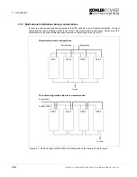
DPA-25
DPA-50
DPA-75
DPA-150
DPA-125
DPA-250
Single Input
Dual Input
PE
B+
BN
B-
1L1
2L1
1L2
2L2
1L3
2L3
1N
2N
PE
3L1
3L2
3L3
3N
PE
E
Batts
Input / Bypass
Output
Содержание PW 9000DPA
Страница 1: ...User Manual Pioneering solutions for total power protection Kohler PW 9000DPA ...
Страница 2: ......
Страница 8: ...iv UPS306 01 00 PowerWAVE 9000 DPA User Manual Dated 01 06 2010 ...
Страница 10: ...1 Safety 1 2 UPS306 01 00 PowerWAVE 9000 DPA User Manual Dated 01 06 2010 ...
Страница 18: ...2 Description 2 8 UPS306 01 00 PowerWAVE 9000 DPA User Manual Dated 01 06 2010 ...
Страница 76: ...7 Options 7 6 UPS306 01 00 PowerWAVE 9000 DPA User Manual Dated 01 06 2010 ...
Страница 85: ...UPS306 01 00 PowerWAVE 9000 DPA User Manual Dated 01 06 2010 8 9 8 Specifications ...
Страница 86: ...8 Specifications 8 10 UPS306 01 00 PowerWAVE 9000 DPA User Manual Dated 01 06 2010 ...


