


TP-6198 3/15
51
Section 5 Component Testing and Adjustment
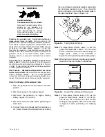
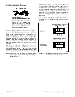
Accidental starting.
Can cause severe injury or death.
Disconnect the battery cables before
working on the generator set.
Remove the negative (--) lead first
when disconnecting the battery.
Reconnect the negative (--) lead last
when reconnecting the battery.
WARNING
Disabling the generator set. Accidental starting can
cause severe injury or death.
Before working on the
generator set or connected equipment, disable the generator
set as follows: (1) Move the generator set master switch to the
OFF position. (2) Disconnect the power to the battery charger.
(3) Remove the battery cables, negative (--) lead first.
Reconnect the negative (--) lead last when reconnecting the
battery. Follow these precautions to prevent starting of the
generator set by an automatic transfer switch, remote
start/stop switch, or engine start command from a remote
computer.
High voltage test. Hazardous voltage can cause severe
injury or death.
Follow the instructions of the test equipment
manufacturer when performing high-voltage tests on the rotor
or stator. An improper test procedure can damage equipment
or lead to generator set failure.
Short circuits. Hazardous voltage/current can cause
severe injury or death.
Short circuits can cause bodily injury
and/or equipment damage
.
Do not contact electrical
connections with tools or jewelry while making adjustments or
repairs. Remove all jewelry before servicing the equipment.
Stator Continuity and Resistance Tests
1. Place the generator set master switch in the OFF
position.
2. Disconnect power to the battery charger.
3. Disconnect the generator set engine starting
battery, negative (--) lead first.
4. Disconnect all stator leads before performing all
stator tests.
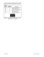
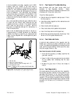
5. To check for stator continuity, set the ohmmeter on
R x 1 scale. First set the ohmmeter zero by holding
the red and black meter leads together and setting
the ohmmeter reading to zero. Then check the
stator continuity by connecting the meter leads to
the stator leads as shown in Figure 5-4.
R14807-14
Figure 5-4
Testing Stator Windings
Note:
For single-phase models, leads 1--4 are the
generator output leads. Leads 11, 44, 55, and 66
are the controller and SCR module sensing and
supply leads.
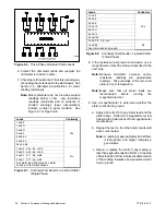
Refer to the schematic in
Figure 5-5 when performing the following steps.
Note:
When taking an ohmmeter reading using lead 55,
make the connection before the inline fuse.
3
4
55
2
1
44
11
6198
66
Figure 5-5
Single-Phase Alternator Stator Leads
Note:
For three-phase models, leads 1--12 are the
generator output leads. Leads V7, V8, V9, 55,
and 66 are the controller and SCR module
sensing and supply leads. Refer to the schematic
in Figure 5-6 when performing the following
steps.
Содержание 15/30RES
Страница 2: ......
Страница 18: ...TP 6198 3 15 18 Section 1 Specifications Notes ...
Страница 62: ...TP 6198 3 15 62 Section 5 Component Testing and Adjustment Notes ...
Страница 71: ......


