


TP-6198 3/15
36 Section 4 Controller
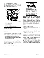
4.6 Relay Interface Board
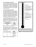
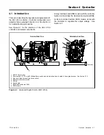
The standard Relay Interface Board (RIB) contains the
K2 crank, K3 flash, and K5 run relays. Three LEDs
indicate relay operation. See Figure 4-7.
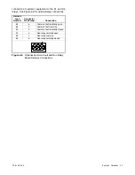
4
GM29671-D
1. K1 common fault relay (optional)
2. K2 crank relay (standard)
3. K3 flash relay (standard)
4. K4 auxiliary run relay (optional)
5. K5 run relay (standard)
6. P14, engine harness connection (standard)
7. P13, connection to optional relay harness (optional)
5
1
2
3
7
6
Figure 4-7
Relay Board
Refer to the schematic diagram in the generator set
wiring diagram manual for the standard relay board
connections.
The RIB is protected by a 10 amp fuse (F2). If the fuse
blows repeatedly, disconnect the board loads one at a
time to identify the cause of the blown fuse:
D
Lead 70A at the fuel select QCON2 connector
D
Lead 71A starter lead at the engine ECM connector
D
Leads FP and FN at the rotor
If fuse continues to blow and disconnecting components
did not identify the cause, remove the leads from the
P14 connector using a pin pusher, part #241918 (large)
or #241919 (small). If replacing the leads does not solve
the problem, replace the RIB.
The individual relays are not replaceable. If one or more
relays are faulty, replace the entire RIB.
Accidental starting.
Can cause severe injury or death.
Disconnect the battery cables before
working on the generator set.
Remove the negative (--) lead first
when disconnecting the battery.
Reconnect the negative (--) lead last
when reconnecting the battery.
WARNING
Disabling the generator set. Accidental starting can
cause severe injury or death.
Before working on the
generator set or connected equipment, disable the generator
set as follows: (1) Move the generator set master switch to the
OFF position. (2) Disconnect the power to the battery charger.
(3) Remove the battery cables, negative (--) lead first.
Reconnect the negative (--) lead last when reconnecting the
battery. Follow these precautions to prevent starting of the
generator set by an automatic transfer switch, remote
start/stop switch, or engine start command from a remote
computer.
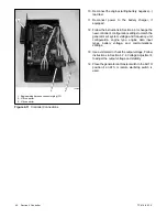
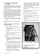
Procedure to Replace the RIB:
1. Place the generator set master switch in the OFF
position.
2. Disconnect power to the battery charger.
3. Disconnect the generator set engine starting
battery, negative (--) lead first.
4. Disconnect P14 and the brush leads FP and FN.
5. Pull the board straight off the mounting stand-offs.
6. Snap the new board onto the stand-offs and
reconnect P14 and the brush leads.
The generator set may be equipped with an optional
RIB, which contains the K4 auxiliary run relay and K1
common fault relay in addition to the standard relays.
The optional relay board kit includes a wiring harness for
Содержание 15/30RES
Страница 2: ......
Страница 18: ...TP 6198 3 15 18 Section 1 Specifications Notes ...
Страница 62: ...TP 6198 3 15 62 Section 5 Component Testing and Adjustment Notes ...
Страница 71: ......


