


TP-6198 3/15
50 Section 5 Component Testing and Adjustment
Hazardous voltage.
Will cause severe injury or death.
This equipment must be installed and
serviced
by
qualified
electrical
personnel.
DANGER
Testing live electrical circuits. Hazardous voltage or
current can cause severe injury or death.
Have trained and
qualified personnel take diagnostic measurements of live
circuits. Use adequately rated test equipment with electrically
insulated probes and follow the instructions of the test
equipment manufacturer when performing voltage tests.
Observe the following precautions when performing voltage
tests: (1) Remove all jewelry. (2) Stand on a dry, approved
electrically insulated mat. (3) Do not touch the enclosure or
components inside the enclosure. (4) Be prepared for the
system to operate automatically.
(600 volts and under)
Short circuits. Hazardous voltage/current can cause
severe injury or death.
Short circuits can cause bodily injury
and/or equipment damage
.
Do not contact electrical
connections with tools or jewelry while making adjustments or
repairs. Remove all jewelry before servicing the equipment.
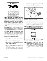
Separate Excitation Procedure
Perform the following procedure to use an external
voltage source to excite the main field (rotor).
1. Disconnect the black FN and FP leads from the
alternator at the SCR module (+) and (--) terminals.
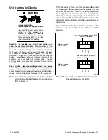
2. Connect a DC ammeter, 10-amp fuse, and a
12-volt automotive battery to the positive (FP) and
negative (FN) brush leads as shown in Figure 5-3.
Note and record the ammeter reading.
Note:
The approximate ammeter reading should
be the battery voltage divided by the
specified rotor resistance. See Section 1,
Specifications, for specified rotor resistance
values.
Example:
12 volts (battery voltage)
3.0 ohms (rotor resistance)
=
4.0 amps
(rotor current)
3. Start the engine and check that the ammeter
reading remains stable. An increasing meter
reading indicates a shorted rotor. A meter reading
decreasing to zero or an unstable reading
suggests a running open. Refer to Section 5.4,
Main Field (Rotor), to test the rotor. If the ammeter
reading is stable, proceed to step 4.
4. Check for AC output across the stator leads; see
Section 5.3, Stator. Compare the readings to the
AC
output
values
shown
in
Section 1,
Specifications. If the readings vary considerably, a
faulty stator is likely. Refer to Section 5.3, Stator,
for further information.
5. If this test shows that the rotor and stator are in
good condition, check the wiring and fuses. Check
the SCR module.
See Section 4.7, Silicon
Controlled Rectifier (SCR) Module. Check the
controller settings and connections.
See
Section 4, Controller.
+
+
1
2 3
4
5
6
7
8
9
TP563274
1. SCR module
2. FN lead disconnected from SCR
3. FP lead disconnected from SCR
4. 10-amp fuse
5. DC ammeter
6. 12V battery
7. Brushes
8. Slip rings
9. Main field (rotor)
FP
FN
Figure 5-3
Separate Excitation Connections
5.3 Stator
The stator contains a series of coils of wire laid in a
laminated steel frame. The stator leads supply AC
voltage to the load and voltage regulator. Before testing
the stator, inspect it for heat discoloration and visible
damage to housing lead wires, exposed coil windings,
and exposed areas of frame laminations. Be sure the
stator is securely fastened to the stator housing.
Note:
Disconnect all stator leads before performing all
stator tests.
Содержание 15/30RES
Страница 2: ......
Страница 18: ...TP 6198 3 15 18 Section 1 Specifications Notes ...
Страница 62: ...TP 6198 3 15 62 Section 5 Component Testing and Adjustment Notes ...
Страница 71: ......


