


Section 2
Installation
20428689
10-2007/Rev 04
2-18
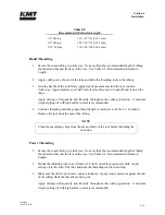
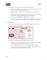
10.
Activate the control power and press the
START
button to start the motor. The dump valve
will open for a short time to allow trapped air to bleed from the high pressure cylinders.
Run the machine in low pressure for approximately five minutes with the orifice removed
to purge the system.
11.
Check for any leaks in the plumbing, or around the high pressure cylinders. If leaks are
detected, stop the machine and correct any problems.
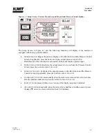
12.
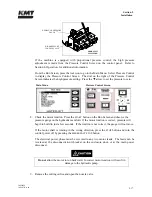
Observe the Booster Pressure Gauge on the front of the machine to ensure the boosted
water pressure peaks between 90-120 psi (6-8 bar) while the intensifier is stroking. If not,
the booster pump pressure must be adjusted. Refer to Section 5, Low Pressure Water
System, for additional information.
Remove the acorn nut on the side of the booster pump and use a flat blade screwdriver to
turn the adjustment screw. Turn the screw clockwise to increase the pressure or counter-
clockwise to decrease the pressure.
13.
Check the safety circuits by pushing the
EMERGENCY STOP
button in and verifying that the
power goes off and high pressure water is drained from the system. If applicable, check
all remote start and emergency stop functions.
14.
Install a large, inexpensive orifice and start the machine.
15.
On the Run Screen, select the
▲
arrow on the
PRESSURE
switch to select high pressure
operation. Increase the high pressure setting in gradual increments, checking for leaks at
each interval. Continue increasing the pressure until the operating pressure is reached.
The high pressure setting is increased by turning the high pressure control valve on the
hydraulic manifold clockwise, or by pressing the
▲
arrow on the Pressure Control Screen.
NOTE
It is strongly recommended that the high pressure plumbing be purged under high
pressure operating conditions, using a large, inexpensive orifice. Contamination
can be released when the tubing expands under pressure. Early orifice failures
could be experienced if the piping is not adequately purged
ACORN
NUT
BOOSTER
PUMP
Содержание STREAMLINE SL-V SRP 100
Страница 1: ...MANUAL 20428408 R08 STREAMLINE SL V SRP 100 WATERJET INTENSIFIER OPERATION AND MAINTENANCE MANUAL ...
Страница 23: ......
Страница 25: ......
Страница 174: ...Section 12 Parts List 20428786 2 2008 Rev 05 12 5 Figure 12 1 SL V SRP 100 Intensifier Unit ...
Страница 176: ...Section 12 Parts List 20428786 2 2008 Rev 05 12 7 Figure 12 2 Intensifier Assembly ...
Страница 180: ...Section 12 Parts List 20428786 2 2008 Rev 05 12 11 Figure 12 5 Pneumatic Valve Actuator Assembly Normally Open ...
Страница 182: ...Section 12 Parts List 20428786 2 2008 Rev 05 12 13 Figure 12 6 Hydraulic Piston Assembly 05136684 ...
Страница 184: ...Section 12 Parts List 20428786 2 2008 Rev 05 12 15 Figure 12 7 High Pressure Piping ...
Страница 186: ...Section 12 Parts List 20428786 2 2008 Rev 05 12 17 Figure 12 8 Low Pressure Water Filter Assembly ...
Страница 188: ...Section 12 Parts List 20428786 2 2008 Rev 05 12 19 Figure 12 9 Hydraulic Power Package ...
Страница 190: ...Section 12 Parts List 20428786 2 2008 Rev 05 12 21 Figure 12 10 Motor Pump Assembly ...
Страница 192: ...Section 12 Parts List 20428786 2 2008 Rev 05 12 23 Figure 12 11 Hydraulic Manifold Assembly ...
Страница 194: ...Section 12 Parts List 20428786 2 2008 Rev 05 12 25 Figure 12 12 Hydraulic Hose Connections ...
Страница 196: ...Section 12 Parts List 20428786 2 2008 Rev 05 12 27 Figure 12 13 Reservoir Assembly ...
Страница 199: ...Section 12 Parts List 20428786 2 2008 Rev 05 12 30 Figure 12 14 Bulkhead Pipe Assembly ...
Страница 201: ...Section 12 Parts List 20428786 2 2008 Rev 05 12 32 Figure 12 15 Cover Assembly ...
Страница 203: ...Section 12 Parts List 20428786 2 2008 Rev 05 12 34 Figure 12 16 Electrical Assembly 200 208 50 60 ...
Страница 205: ...Section 12 Parts List 20428786 2 2008 Rev 05 12 36 Figure 12 17 Electrical Assembly 230 50 60 ...
Страница 207: ...Section 12 Parts List 20428786 2 2008 Rev 05 12 38 Figure 12 18 Electrical Assembly 380 415 50 60 ...
Страница 210: ...Section 12 Parts List 20428786 2 2008 Rev 05 12 41 Figure 12 19 Controls Subassembly 200 208 230 50 60 ...
Страница 213: ...Section 12 Parts List 20428786 2 2008 Rev 05 12 44 Figure 12 20 Controls Subassembly 380 415 50 60 ...
Страница 215: ...Section 12 Parts List 20428786 2 2008 Rev 05 12 46 Figure 12 21 Control Panel Configuration 200 208 50 60 ...
Страница 217: ...Section 12 Parts List 20428786 2 2008 Rev 05 12 48 Figure 12 22 Control Panel Configuration 230 50 60 ...
Страница 219: ...Section 12 Parts List 20428786 2 2008 Rev 05 12 50 Figure 12 23 Control Panel Configuration 380 415 50 60 ...
Страница 221: ...Section 12 Parts List 20428786 2 2008 Rev 05 12 52 Figure 12 24 Proportional Pressure Control 80075732 ...
Страница 223: ...Section 12 Parts List 20428786 2 2008 Rev 05 12 54 Figure 12 25 High Pressure Transducer ...
Страница 224: ......
Страница 225: ......
Страница 226: ......
Страница 227: ......
Страница 228: ......
Страница 229: ......
Страница 230: ......
Страница 231: ......
Страница 232: ......
Страница 233: ......
Страница 234: ......
Страница 235: ......
Страница 236: ......
Страница 237: ......
Страница 238: ......
Страница 239: ......


