


20428689
10-2007/Rev 04
2-1
SECTION 2
INSTALLATION
2.1
Overview
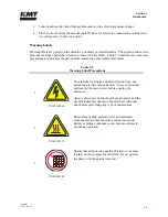
Installation and commissioning requirements and procedures are detailed in this section. These
procedures require a thorough understanding of the individual components and systems, safety
issues, and the overall operation of the intensifier.
All personnel involved in the installation, operation and/or service of the intensifier must
carefully review this manual prior to installing and commissioning the machine.
The Technical Service Department at KMT Waterjet Systems is available to assist in the
installation and commissioning process. Service and repair training for maintenance personnel is
also available.
2.2
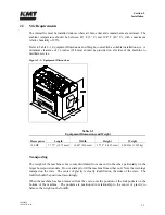
Installation Summary
The following summary lists the procedures required for the installation and commissioning of
the intensifier system. Details and requirements for each item are discussed in this section.
•
Upon receipt, the machine must be uncrated and moved into position on a level surface.
•
Properly sized power drops with fused disconnects must be installed.
•
A pneumatic drop with a manual shutoff valve and regulator for the air connection must
be installed.
•
Plumbing and manual shutoff valves for the inlet and outlet cooling water, and the inlet
and outlet cutting water must be installed.
Incoming source water must meet specific water quality standards, flow rates and pressure
requirements. It may be necessary to install water conditioning and/or pressure boosting
equipment to meet these water purity and pressure requirements.
•
Drain water plumbing must be suitably located and installed for the proper disposal of
wastewater.
•
High pressure tubing runs from the intensifier to the cutting station must be installed with
the appropriate mountings, support brackets and hardware.
•
Wiring must be installed and connected between the intensifier and the cutting station
control system.
•
The machine must be commissioned and tested.
Содержание STREAMLINE SL-V SRP 100
Страница 1: ...MANUAL 20428408 R08 STREAMLINE SL V SRP 100 WATERJET INTENSIFIER OPERATION AND MAINTENANCE MANUAL ...
Страница 23: ......
Страница 25: ......
Страница 174: ...Section 12 Parts List 20428786 2 2008 Rev 05 12 5 Figure 12 1 SL V SRP 100 Intensifier Unit ...
Страница 176: ...Section 12 Parts List 20428786 2 2008 Rev 05 12 7 Figure 12 2 Intensifier Assembly ...
Страница 180: ...Section 12 Parts List 20428786 2 2008 Rev 05 12 11 Figure 12 5 Pneumatic Valve Actuator Assembly Normally Open ...
Страница 182: ...Section 12 Parts List 20428786 2 2008 Rev 05 12 13 Figure 12 6 Hydraulic Piston Assembly 05136684 ...
Страница 184: ...Section 12 Parts List 20428786 2 2008 Rev 05 12 15 Figure 12 7 High Pressure Piping ...
Страница 186: ...Section 12 Parts List 20428786 2 2008 Rev 05 12 17 Figure 12 8 Low Pressure Water Filter Assembly ...
Страница 188: ...Section 12 Parts List 20428786 2 2008 Rev 05 12 19 Figure 12 9 Hydraulic Power Package ...
Страница 190: ...Section 12 Parts List 20428786 2 2008 Rev 05 12 21 Figure 12 10 Motor Pump Assembly ...
Страница 192: ...Section 12 Parts List 20428786 2 2008 Rev 05 12 23 Figure 12 11 Hydraulic Manifold Assembly ...
Страница 194: ...Section 12 Parts List 20428786 2 2008 Rev 05 12 25 Figure 12 12 Hydraulic Hose Connections ...
Страница 196: ...Section 12 Parts List 20428786 2 2008 Rev 05 12 27 Figure 12 13 Reservoir Assembly ...
Страница 199: ...Section 12 Parts List 20428786 2 2008 Rev 05 12 30 Figure 12 14 Bulkhead Pipe Assembly ...
Страница 201: ...Section 12 Parts List 20428786 2 2008 Rev 05 12 32 Figure 12 15 Cover Assembly ...
Страница 203: ...Section 12 Parts List 20428786 2 2008 Rev 05 12 34 Figure 12 16 Electrical Assembly 200 208 50 60 ...
Страница 205: ...Section 12 Parts List 20428786 2 2008 Rev 05 12 36 Figure 12 17 Electrical Assembly 230 50 60 ...
Страница 207: ...Section 12 Parts List 20428786 2 2008 Rev 05 12 38 Figure 12 18 Electrical Assembly 380 415 50 60 ...
Страница 210: ...Section 12 Parts List 20428786 2 2008 Rev 05 12 41 Figure 12 19 Controls Subassembly 200 208 230 50 60 ...
Страница 213: ...Section 12 Parts List 20428786 2 2008 Rev 05 12 44 Figure 12 20 Controls Subassembly 380 415 50 60 ...
Страница 215: ...Section 12 Parts List 20428786 2 2008 Rev 05 12 46 Figure 12 21 Control Panel Configuration 200 208 50 60 ...
Страница 217: ...Section 12 Parts List 20428786 2 2008 Rev 05 12 48 Figure 12 22 Control Panel Configuration 230 50 60 ...
Страница 219: ...Section 12 Parts List 20428786 2 2008 Rev 05 12 50 Figure 12 23 Control Panel Configuration 380 415 50 60 ...
Страница 221: ...Section 12 Parts List 20428786 2 2008 Rev 05 12 52 Figure 12 24 Proportional Pressure Control 80075732 ...
Страница 223: ...Section 12 Parts List 20428786 2 2008 Rev 05 12 54 Figure 12 25 High Pressure Transducer ...
Страница 224: ......
Страница 225: ......
Страница 226: ......
Страница 227: ......
Страница 228: ......
Страница 229: ......
Страница 230: ......
Страница 231: ......
Страница 232: ......
Страница 233: ......
Страница 234: ......
Страница 235: ......
Страница 236: ......
Страница 237: ......
Страница 238: ......
Страница 239: ......


