


Section 9
High Pressure Water System
20428754
7-2007/Rev 03
9-12
NOTE
If galling occurs during threading, remove the high pressure cylinder assembly and
inspect the mating surfaces and threads. Repair surfaces, thoroughly clean,
lubricate and thread the cylinder assembly into the hydraulic cylinder head.
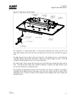
NOTE
An alignment mark is located on the hydraulic cylinder head under the KMT logo.
To ensure the high pressure cylinder is properly tightened and fully seated in the
hydraulic cylinder head, it is recommended that a corresponding mark be placed on
the high pressure cylinder after installation. Periodically inspect the cylinder for
movement. If movement is detected, retighten the assembly.
4.
Connect the high and low pressure water piping, following the procedure, High and Low
Pressure Water Piping.
5.
Start the machine in low pressure mode to flush air from the high pressure components
and to check for obvious leaks. After 5-10 strokes, switch to high pressure operation and
check for leaks.
If leaks are detected, turn the machine off and remedy the problem. When the problem
has been remedied, repeat the start up procedure, moving from low to high pressure soon
after the intensifier starts pumping water. There is no further need to flush air from the
system.
High Pressure Cylinder Maintenance
The plunger seal area in the high pressure cylinder bore should be inspected and cleaned each
time the high pressure seal assembly is replaced.
1.
Clean the sealing area on the inside diameter of the high pressure cylinder and inspect the
bore for rings, scratches, pits, residue or other potential leak paths.
Seal material or residue can build up, forming a ring. Running a fingernail across the
buildup will cause it to appear as a surface flaw. Grooves or ridges are typically seal
debris buildup rather than marks on the inside diameter wall of the cylinder.
2.
Polish the inside diameter of the cylinder where the seal will locate with 600-grit wet/dry
sandpaper. Hold the sandpaper on the end of your finger and move in a cylindrical wiping
motion. Polish in a circumferential motion only. Do not polish or drag the sandpaper
along the length of the cylinder.
3.
Clean the residue from the inside diameter of the cylinder and re-inspect for surface
defects.
Содержание STREAMLINE SL-V SRP 100
Страница 1: ...MANUAL 20428408 R08 STREAMLINE SL V SRP 100 WATERJET INTENSIFIER OPERATION AND MAINTENANCE MANUAL ...
Страница 23: ......
Страница 25: ......
Страница 174: ...Section 12 Parts List 20428786 2 2008 Rev 05 12 5 Figure 12 1 SL V SRP 100 Intensifier Unit ...
Страница 176: ...Section 12 Parts List 20428786 2 2008 Rev 05 12 7 Figure 12 2 Intensifier Assembly ...
Страница 180: ...Section 12 Parts List 20428786 2 2008 Rev 05 12 11 Figure 12 5 Pneumatic Valve Actuator Assembly Normally Open ...
Страница 182: ...Section 12 Parts List 20428786 2 2008 Rev 05 12 13 Figure 12 6 Hydraulic Piston Assembly 05136684 ...
Страница 184: ...Section 12 Parts List 20428786 2 2008 Rev 05 12 15 Figure 12 7 High Pressure Piping ...
Страница 186: ...Section 12 Parts List 20428786 2 2008 Rev 05 12 17 Figure 12 8 Low Pressure Water Filter Assembly ...
Страница 188: ...Section 12 Parts List 20428786 2 2008 Rev 05 12 19 Figure 12 9 Hydraulic Power Package ...
Страница 190: ...Section 12 Parts List 20428786 2 2008 Rev 05 12 21 Figure 12 10 Motor Pump Assembly ...
Страница 192: ...Section 12 Parts List 20428786 2 2008 Rev 05 12 23 Figure 12 11 Hydraulic Manifold Assembly ...
Страница 194: ...Section 12 Parts List 20428786 2 2008 Rev 05 12 25 Figure 12 12 Hydraulic Hose Connections ...
Страница 196: ...Section 12 Parts List 20428786 2 2008 Rev 05 12 27 Figure 12 13 Reservoir Assembly ...
Страница 199: ...Section 12 Parts List 20428786 2 2008 Rev 05 12 30 Figure 12 14 Bulkhead Pipe Assembly ...
Страница 201: ...Section 12 Parts List 20428786 2 2008 Rev 05 12 32 Figure 12 15 Cover Assembly ...
Страница 203: ...Section 12 Parts List 20428786 2 2008 Rev 05 12 34 Figure 12 16 Electrical Assembly 200 208 50 60 ...
Страница 205: ...Section 12 Parts List 20428786 2 2008 Rev 05 12 36 Figure 12 17 Electrical Assembly 230 50 60 ...
Страница 207: ...Section 12 Parts List 20428786 2 2008 Rev 05 12 38 Figure 12 18 Electrical Assembly 380 415 50 60 ...
Страница 210: ...Section 12 Parts List 20428786 2 2008 Rev 05 12 41 Figure 12 19 Controls Subassembly 200 208 230 50 60 ...
Страница 213: ...Section 12 Parts List 20428786 2 2008 Rev 05 12 44 Figure 12 20 Controls Subassembly 380 415 50 60 ...
Страница 215: ...Section 12 Parts List 20428786 2 2008 Rev 05 12 46 Figure 12 21 Control Panel Configuration 200 208 50 60 ...
Страница 217: ...Section 12 Parts List 20428786 2 2008 Rev 05 12 48 Figure 12 22 Control Panel Configuration 230 50 60 ...
Страница 219: ...Section 12 Parts List 20428786 2 2008 Rev 05 12 50 Figure 12 23 Control Panel Configuration 380 415 50 60 ...
Страница 221: ...Section 12 Parts List 20428786 2 2008 Rev 05 12 52 Figure 12 24 Proportional Pressure Control 80075732 ...
Страница 223: ...Section 12 Parts List 20428786 2 2008 Rev 05 12 54 Figure 12 25 High Pressure Transducer ...
Страница 224: ......
Страница 225: ......
Страница 226: ......
Страница 227: ......
Страница 228: ......
Страница 229: ......
Страница 230: ......
Страница 231: ......
Страница 232: ......
Страница 233: ......
Страница 234: ......
Страница 235: ......
Страница 236: ......
Страница 237: ......
Страница 238: ......
Страница 239: ......


